
LOW frequency square wave oscillator circuit
Warning: Undefined array key "extension" in /var/www/html/nextgr/view-circuit.php on line 468
Deprecated: strtolower(): Passing null to parameter #1 ($string) of type string is deprecated in /var/www/html/nextgr/view-circuit.php on line 468

To construct a circuit that produces an inverted square wave, a basic approach involves using a 555 timer IC configured in astable mode. In this configuration, the 555 timer generates a continuous square wave output. For inversion, the output can be fed through a transistor or an inverter gate.
The circuit setup begins with the 555 timer connected in astable mode. Resistor R1 and resistor R2, along with capacitor C1, determine the frequency and duty cycle of the output waveform. The values of R1 and R2 can be calculated using the formula:
\[ f = \frac{1.44}{(R1 + 2R2) \cdot C1} \]
Where:
- \( f \) is the frequency of the output square wave.
- \( R1 \) and \( R2 \) are the resistances in ohms.
- \( C1 \) is the capacitance in farads.
For the inversion, the output from the 555 timer (pin 3) is connected to the base of an NPN transistor through a current-limiting resistor. The emitter is grounded, while the collector is connected to a positive voltage supply through a load resistor. When the output from the 555 timer goes high, the transistor turns on, pulling the output low, and when the timer output goes low, the transistor turns off, allowing the output to go high. This configuration effectively inverts the square wave produced by the timer.
Alternatively, a logic inverter (such as a 74HC14) can be used to achieve the same effect. The output from the 555 timer is connected to the input of the inverter, and the output of the inverter will provide the inverted square wave.
This simple circuit can be powered by a standard DC power supply, and with the appropriate component selection, it can be fine-tuned for specific frequency requirements.A real simple circuit that I can make that will give me the same inverted square wave the inventor is using The inventor calls out the setup he used on his funtion generator. 🔗 External reference
Related Circuits
The industrial fuel oil furnace controller circuit consists of a power supply circuit, a testing and ignition control circuit, and a control implementation circuit, as illustrated in the accompanying diagram. The power supply circuit includes a step-down capacitor (C6),...
This simple circuit is the electronic version of the combination lock. Using the special purpose LS7220 digital lock IC, the circuit allows a 4 digit combination of your choice to activate a relay for a set period of time....
The current generated flows through clips placed on the earlobes. The output current is adjustable from 80 to 600 microamperes, following the recent launch in Europe. The described device utilizes a current generation mechanism that delivers a controlled microcurrent through...
The circuit incorporates components Q, C, and ZD, which are responsible for the bias and buffer stages. Its primary objective is to ensure stable MOSFET gate operation and provide an offset voltage through a voltage buffer amplifier stage with...
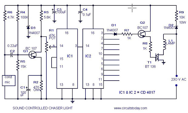
A simple musical light chaser circuit diagram and schematic using IC CD4016. This circuit blinks lights in response to sound, audio, or music output, causing 10 lights to dance according to sound frequency. The musical light chaser circuit utilizing the...
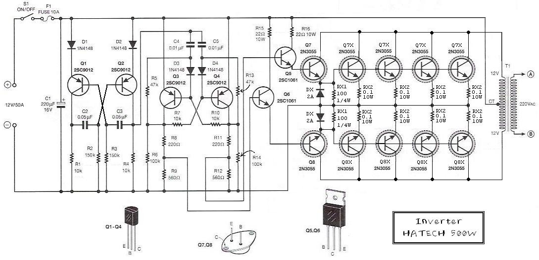
This is the schematic diagram of a 500W power inverter circuit built using 10 pieces of well-known NPN power transistors, 2N3055, to amplify the AC signal produced by a multivibrator. The frequency generator/multivibrator is also constructed using transistors. All...