
Automatic Room Lights With NE555 IC

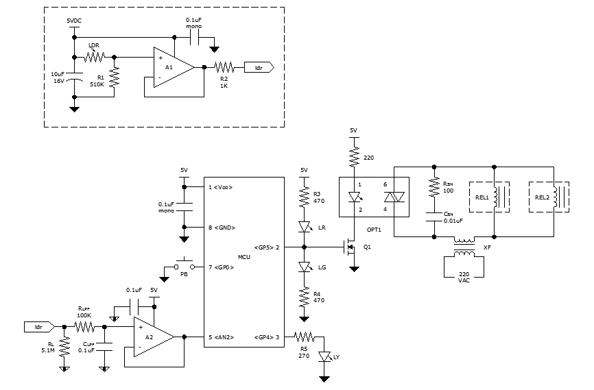
The automatic room light circuit is designed to enhance energy efficiency and convenience by utilizing a memory component, typically a flip-flop or a microcontroller, to control the lighting based on occupancy or ambient light levels. The circuit generally consists of several key components: a light sensor, a relay, a memory element, and a power supply.
The light sensor, often a photoresistor or phototransistor, detects the ambient light level in the room. When the light level drops below a certain threshold, indicating that it is dark, the sensor sends a signal to the memory component. The memory component retains the state of the circuit, ensuring that the light remains on until the sensor detects sufficient ambient light, at which point it sends a signal to switch off the light.
The relay acts as a switch that controls the power to the light fixture. When activated by the memory component, the relay closes the circuit, allowing current to flow to the light bulb, thus illuminating the room. Conversely, when the memory component receives a signal from the light sensor indicating that the ambient light level is adequate, the relay opens, cutting off the power to the light bulb.
The power supply provides the necessary voltage and current to operate the circuit components. It is crucial to ensure that the power supply is compatible with the specifications of the light bulb and the control circuitry.
This circuit can be further enhanced with additional features, such as adjustable sensitivity for the light sensor, a timer to limit the duration the light stays on, or integration with a motion sensor for increased automation. These enhancements can improve the responsiveness and functionality of the automatic room light circuit, making it suitable for various applications in residential and commercial settings.This circuit shows an automatic room light circuit diagram. It has a small memory which enables it to automatically switch `on` and switch `off` .. 🔗 External reference
Related Circuits
This calculator computes the resistor and capacitor values for a NE555 timer chip configured as an astable multivibrator (oscillator) or square wave generator. By entering the desired duty cycle and frequency, the calculator provides suitable values for the resistors...
This circuit triggers an alarm when its LDR (Light Dependent Resistor) sensor is exposed to light from the sun or a lamp. A 555 astable multivibrator is utilized to generate a tone of approximately 1 kHz upon detecting light....
While discussing an all-linear automatic night light circuit, it was mentioned that an MCU-based Automatic Night Light Controller (ANLC) was being tested. The firmware has been tweaked since then. Recently, the sensor was installed outdoors and connected to control...
Using high-beam headlights can significantly enhance visibility while driving, but they can also pose a blinding hazard to other drivers. A simple circuit can be integrated into the headlight system to enable automatic switching between high and low beam...
A 2001 Chevrolet Cavalier has experienced a failure in one of the low beam headlights. Despite replacing the bulb, the headlight remains non-functional. Additionally, when the vehicle is shifted into gear, the daytime running lights flash multiple times before...
The switch control system utilizes sensors to inform the microcontroller of the trains' positions on the layout. This ensures that only one train occupies the main line at any given time and that switches are correctly set for the...
Warning: include(partials/cookie-banner.php): Failed to open stream: Permission denied in /var/www/html/nextgr/view-circuit.php on line 713
Warning: include(): Failed opening 'partials/cookie-banner.php' for inclusion (include_path='.:/usr/share/php') in /var/www/html/nextgr/view-circuit.php on line 713