
Microcontroller-based automatic night light circuit

The automatic night light circuit described operates using a microcontroller (MCU) that processes inputs from a light-dependent resistor (LDR) to control the activation of outdoor lighting based on ambient light levels. The LDR serves as the primary sensor, detecting changes in light intensity and providing a variable resistance that the MCU interprets through an analog-to-digital converter (ADC). The firmware logic includes thresholds for determining when to turn the lights on or off, incorporating hysteresis to avoid rapid cycling due to transient light changes.
The physical setup of the sensor is crucial for accurate readings; positioning the LDR on the roof with a zenith orientation minimizes interference from artificial light sources. The translucent housing protects the LDR while allowing sufficient light penetration for accurate measurements. The use of a unity gain buffer ensures that the high impedance output of the LDR is transformed into a low impedance signal suitable for processing by the MCU, which is essential for maintaining signal integrity and avoiding noise interference.
The low-pass filter implemented on the control board plays a vital role in filtering out high-frequency noise that could disrupt the ADC readings, particularly in environments prone to electromagnetic interference. The design choice of including a high-value load resistor (RL) acts as a fail-safe mechanism, ensuring the circuit behaves predictably in the event of a sensor cable failure.
User interaction is facilitated through a push button (PB) that allows manual setting of the light activation threshold. This feature, combined with EEPROM storage, enables the user to customize the light level at which the circuit will activate the load, enhancing the versatility of the night light system. The indicator light (LY) provides visual feedback during the configuration process, ensuring the user is informed of the current settings.
Overall, the circuit design emphasizes reliability, user configurability, and adaptability to varying ambient conditions, making it suitable for outdoor lighting applications where accurate light sensing is critical.While discussing an all-linear automatic night light circuit I mentioned that I was testing an MCU-based ANLC. Well, I`ve been tweaking the firmware since. The other day I installed the sensor outdoors and have connected the circuit to control 220VAC loads.
Last night the circuit got fooled when clouds moved in at around 2am and reflected sufficie nt city lights and streetlights that the MCU thought it was already the beginning of dawn and switched off the load. This is because the software algorithm is such that a 10-bit ADC change of just 0x00A from the average dark ambient light level is interpreted as dawn.
Competent programmer that I am, the firmware also includes a conditional which turns the load back on again should the light level drop back to the average dark level. And some half hour or an hour later (not sure because I went back to sleep before waking up again some time later) it did actually did return to dark level conditions.
A sonalert buzzer is temporarily hooked up such that it sounds when the load (perimeter security lights) is off and as far as I know (sleepy head that I am) the next time the load was switched off by the circuit was around 5am-true dawn. Earlier that same evening at around midnight while remotely monitoring the voltage output of the sensor ("ldr" in the schematic) with a DMM I was surprised to see the numbers climbing rapidly.
The output had already settled at ~20mV but then increased quickly within minutes and peaked at ~310mV. I had to look out the window just to make sure I wasn`t witnessing a circuit glitch but that in fact ambient light level was shooting up.
And true enough the sky had turned orange and bright-from the cloud cover. The circuit did not turn the load off because the firmware was using a different hysteresis value at that time. Only after the load has been on for six hours does it use the hysteresis value of ten (the 10-bit ADC value mentioned above).
By 2am this six hours had already elapsed. Because of the detection sensitivity used, the light sensor circuit is located on the roof to minimize being affected by artificial lights. The LDR faces directly up (zenith) and is housed in a translucent plastic box. The box is shielded on the sides to prevent streetlights and lights from nearby buildings and billboards from unduly affecting the sensor.
The very high impedance output of the sensor requires a unity gain buffer. The LDR used has a resistance of >30Mohms in complete darkness. On the main control board, a low pass filter comprised of RLPF and CLPF (cut off frequency = 1/(2 RC) = 1/(6. 28*100K*0. 1uF) = 16Hz) attenuates high frequency noise which could be caused by EMI particularly those from lightning.
A unity gain buffer is used to provide a low impedance signal for the MCU. High value load resistor RL is used because in the event that the cable to the sensor breaks, the input of the LPF and buffer will not be left floating. In such an event RL grounds the input, fooling the MCU to think that it`s nighttime and thus turning on the load.
This serves to alert the user (in the daytime) of a malfunction. PB is used to select the light level at which load will be turned on. The user waits until the ambient light level is at the point where s/he wants the load switched on. At that moment PB is pressed. The circuit stores the light level in EEPROM and uses this value until it is changed. Pressing and holding down PB for a second resets the value to its minimum (I arbitrarily set it ADC value 0x064)-meaning load will be turned on only when it`s really dark. LY is the indicator light for PB. It flashes briefly when PB is pressed (falling edge detected) and it blinks on and off for 1. 5s when the trip level has been reset to minimum. A debouncing routine is used to, well, debounce PB, detect falling/rising edges, and monitor how long PB has been depressed.
REL1 and REL2 are mini relays with 24VAC coil. They are sw 🔗 External reference
Related Circuits
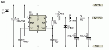
This is a voltage doubling circuit built using the well-known timer IC 555. The circuit is straightforward and easy to construct. The construction is not critical. Rectifier diodes should be ultrafast (such as UF4004 or similar), or 1N4148 signal...
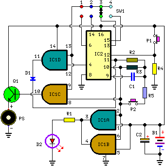
This circuit is designed for alerting purposes after a predetermined time has elapsed. It is ideal for tabletop games that require a fixed duration for answering questions or moving pieces. In this context, it serves as a modern alternative...

Application of the differential amplifier circuit in OTL amplifier circuits. The differential amplifier circuit is a fundamental building block in various electronic applications, particularly in output transformerless (OTL) amplifier circuits. An OTL amplifier is designed to drive loads directly...
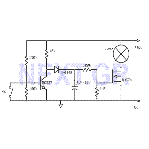
This circuit gradually switches the internal lights of a car on and off. The delay time can be adjusted by changing the values of the 10k and 4.7M resistors, as well as the capacitor. The circuit operates by utilizing a...
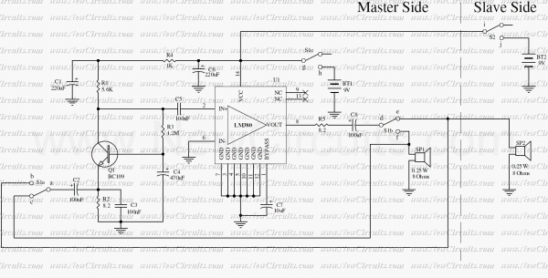
Very simple and useful circuit for communication between two persons. The Q1 is used to amplify the weak output signal of the speaker when one pushes his (her) side push-button to speak. The base-common configuration of the Q1 pre-amplifier...
This is a simple siren sound generator with high power output and significant noise levels. The circuit utilizes digital integrated circuits (ICs), specifically the CD4046, in an inverter configuration along with four transistors to increase the current output to...