
Simple Light Sensor Alarm circuit with NE555
The circuit employs a 555 timer configured in an astable mode, which is ideal for generating a continuous square wave output. The LDR serves as a light-sensitive resistor whose resistance decreases significantly when exposed to light, thus allowing current to flow through the circuit. The output frequency of the 555 timer is determined by the resistor and capacitor values connected to it, with the frequency approximately set at 1 kHz in this application.
In this design, the LDR is connected in series with a resistor to form a voltage divider. When light falls on the LDR, its resistance drops, resulting in a higher voltage at the input of the 555 timer, triggering it to oscillate. The output from the 555 timer is fed into a transistor, which acts as a switch to control a larger load, such as a buzzer or alarm system.
The sensitivity adjustment feature, implemented through potentiometer P1, allows for fine-tuning of the light threshold at which the alarm activates. By varying the resistance, the circuit can be made more or less responsive to changes in light levels, providing flexibility in different lighting conditions.
Overall, this circuit is a practical solution for creating a light-activated alarm system, suitable for various applications such as security systems or alert mechanisms in environments where light levels need monitoring. The simplicity of the 555 timer circuit combined with the LDR sensor provides an effective and cost-efficient method for detecting light and activating an alarm.This circuit sent out an alarm when its LDR sensor is exposed to light by sun or lamp. A 555 astable multivibrator was used here which sent signal a tone of about 1kHz upon detecting light. The sensor when exposed by light completes the circuit and makes the 555 oscillate at about 1kHz with transistor to drive current.
Sensitivity can be adjust wit h P1. This makes the sun light to flow through it to the ground and prevents the alarm from going on due to the stored light on the sensor. 🔗 External reference
Related Circuits
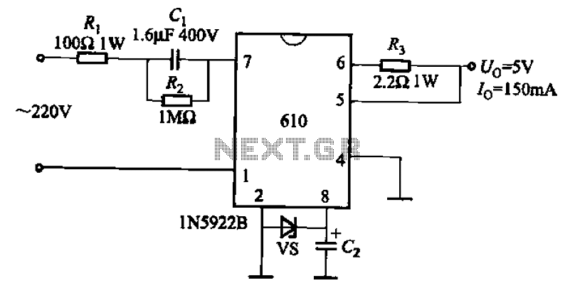
The AX610 Series has a maximum output current of 100 mA and features a scalable output current with an access regulator. The configuration includes two reverse polarity series regulators (2CW106, U: approximately 8.2V) as depicted in Figure (a). Figure...
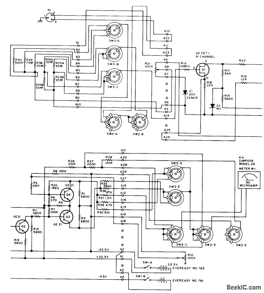
This circuit utilizes a probe that contains a Clairex 905HN light-dependent resistance element, which is connected to a DC differential amplifier. The amplifier drives a meter with a specially calibrated scale. The article outlines the calibration procedure. A switching...
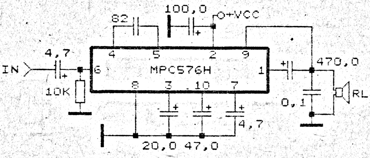
This amplifier circuit exhibits good sound quality. Although it does not provide high output power, it is capable of producing both soft and loud sounds reliably. The circuit utilizes a single IC, the MPC576H, along with several supporting components....
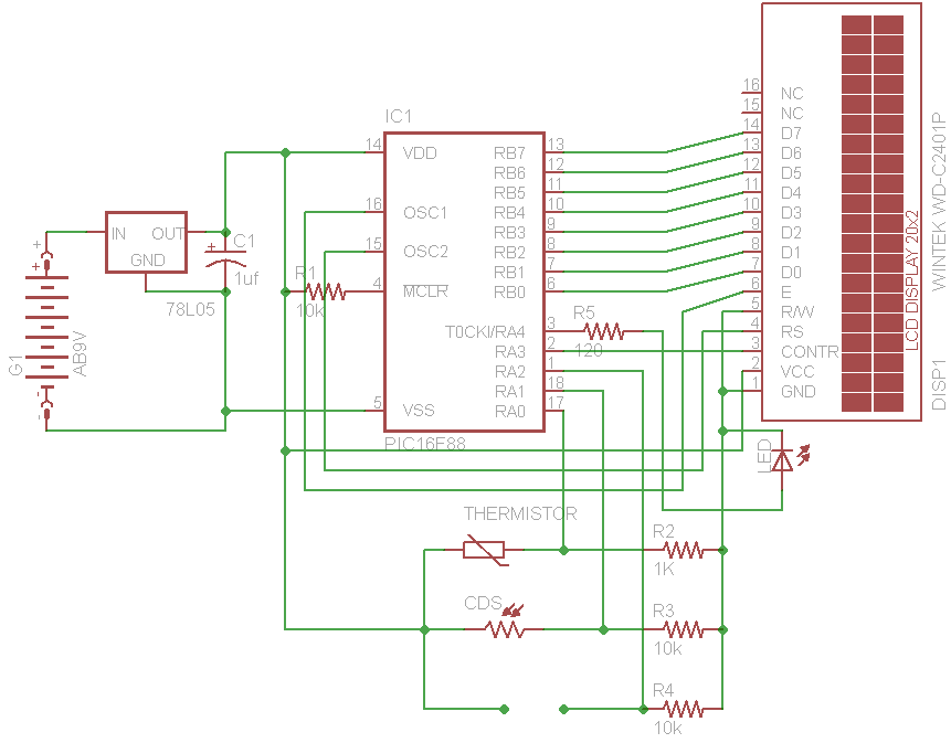
The initial concept for this project involves interfacing the WINTEK WD-C2401P LCD panel with a PIC microcontroller. The intention is to incorporate several ADC readings to provide useful information on the LCD. PORTB on the PIC serves as the...
The circuit of the unit is fairly simple, but is a bit irksome to set up. The reason is that obtaining matched FETs is not easy, so I had to make sure that the circuit would work with off-the-shelf...
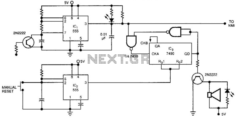
The watchdog timer includes a counter, IC3, alongside the standard retriggerable 555 timer, IC1. The counter will sound an audible alarm if the watchdog timer attempts to reset a specified number of times (8, in the case of the...