
Automatic safety flasher
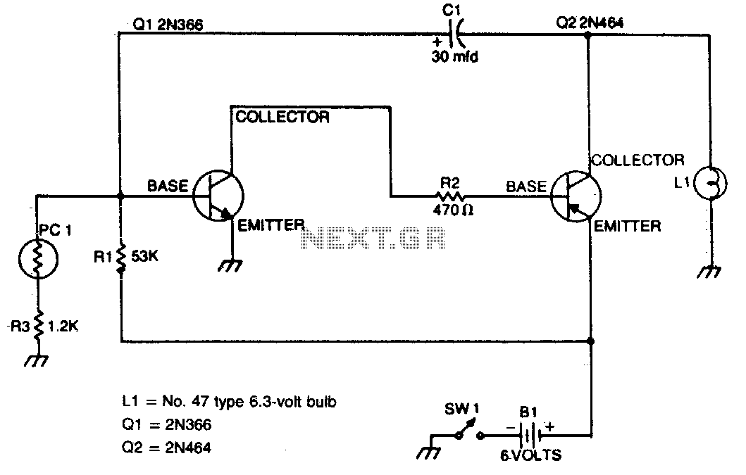
The circuit for the nighttime flasher utilizes a photocell sensor to control the operation of the light source. The photocell, also known as a light-dependent resistor (LDR), plays a critical role in the functionality of the device. When ambient light levels fall below a certain threshold, the resistance of the LDR decreases, allowing current to flow through the circuit and activating the flasher.
The circuit typically consists of a power supply, the photocell, a relay or transistor for switching, and the light source, which may be an LED or incandescent bulb. The photocell is connected in series with a resistor to form a voltage divider. As the light level decreases at dusk, the voltage across the photocell and resistor changes, triggering the relay or transistor to close the circuit and turn on the light.
To prevent the light from turning on during the day, the photocell must be mounted in a location that receives maximum exposure to sunlight. This ensures reliable operation and prevents unnecessary power consumption during daylight hours. The relay or transistor used in the circuit should be rated for the current and voltage of the light source to ensure safe and effective operation.
Additionally, a delay circuit may be incorporated to prevent flickering during twilight hours when light levels fluctuate. This can be achieved using a simple RC (resistor-capacitor) timing circuit that introduces a short delay before the light turns off after sunrise.
Overall, this schematic design emphasizes efficiency and reliability, ensuring that the flasher operates as intended while providing optimal illumination during the night.This flasher only comes on at night. It furnishes a bright nighttime illumination, and shuts itself off automatically as soon as the sun comes up The photocell must be mounted on top of the unit in such a way as to detect the greatest amount of available light. 🔗 External reference
Related Circuits
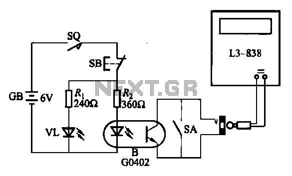
An electronic calculator features an automatic counting interface circuit, as illustrated in the accompanying figures. Figure (a) depicts a stroke switch controlled via optocoupler B. Figure (b) shows the application of a reed switch (KR) for pulse control signals....
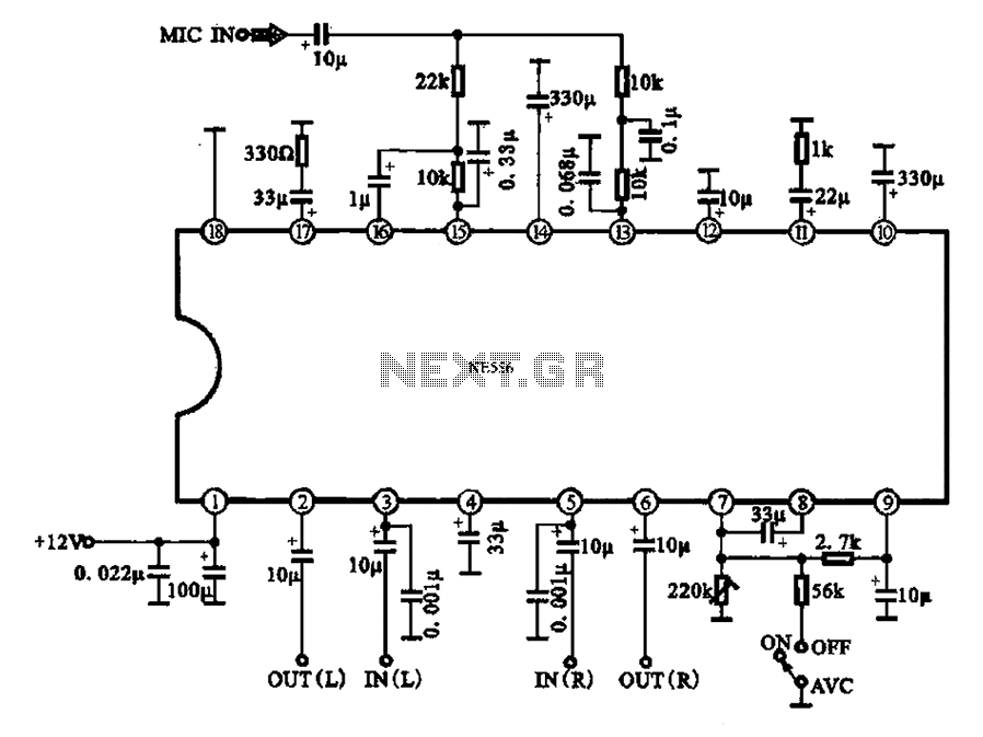
Automatic volume adjustment with ambient noise control circuit. In car stereos and similar devices, the ambient noise level varies during high-speed and low-speed driving or while stationary, leading to different volume requirements. A fixed volume adjustment method may negatively...
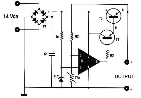
This automatic battery charger circuit is ideal for charging batteries used in alarm systems that require battery buffering. Caution must be exercised when connecting the battery to ensure correct AC polarity. It is essential to meticulously follow the schematic...
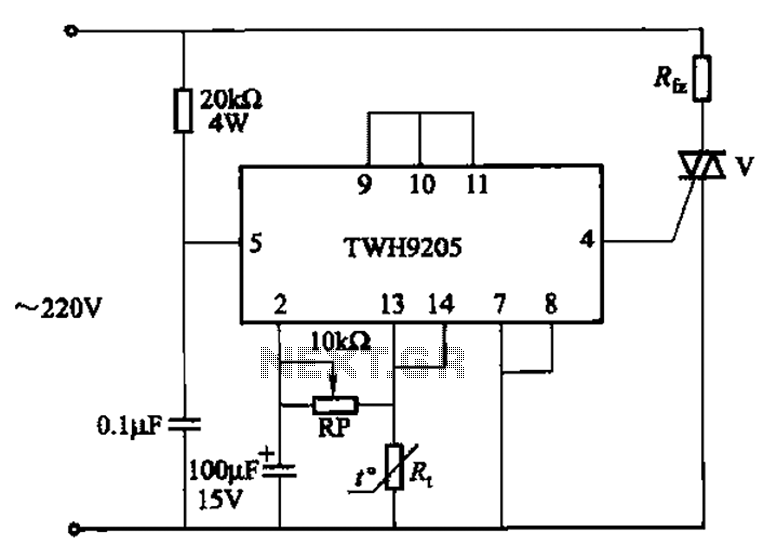
This circuit is used for temperature control in various heating equipment such as water heaters, microwave ovens, air conditioners, refrigerators, fans, and automatic fire extinguishing devices. It includes a negative temperature coefficient (NTC) thermistor as the temperature sensing element...
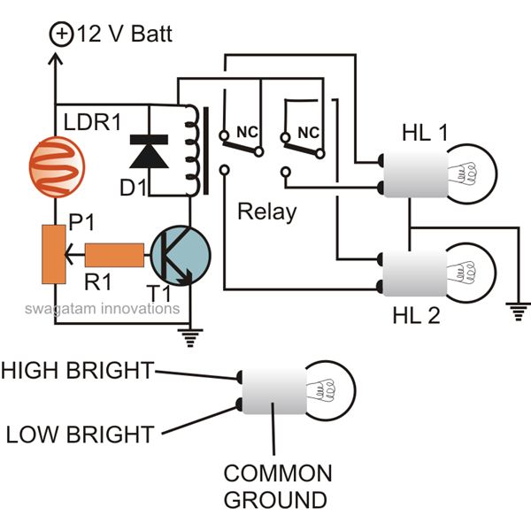
The circuit described here can be built and used in a vehicle for an automatic dipping and dimming operation of the headlamps in response to intense lights coming from opposite vehicle headlamps. This situation is often encountered while driving...
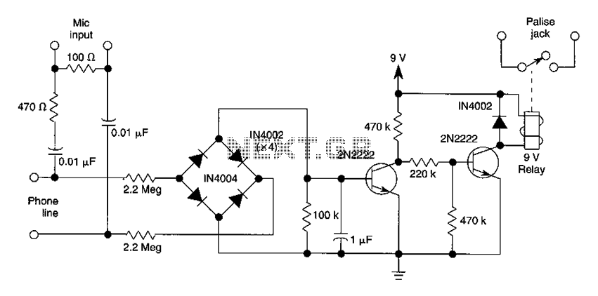
The DC voltage present on the telephone line typically ranges from 45 to 50V when on-hook and drops to approximately 6V when off-hook. This condition activates a step-down circuit relay, which in turn controls a tape recorder. Audio input...
Warning: include(partials/cookie-banner.php): Failed to open stream: Permission denied in /var/www/html/nextgr/view-circuit.php on line 713
Warning: include(): Failed opening 'partials/cookie-banner.php' for inclusion (include_path='.:/usr/share/php') in /var/www/html/nextgr/view-circuit.php on line 713