
Electronic counter with automatic counting interface circuit a
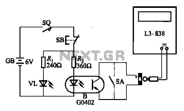
The electronic calculator's automatic counting interface circuit is designed to enhance functionality and reliability in counting applications. The stroke switch depicted in Figure (a) serves as an initial input mechanism, enabling user interaction with the system. The optocoupler B acts as an isolator, ensuring that the control signals from the stroke switch do not interfere with the main circuit, thus maintaining signal integrity.
In Figure (b), the reed switch (KR) is employed to generate pulse control signals. This component operates based on magnetic fields, providing a reliable means of detecting the presence of an object or user action, which in turn generates a pulse that can be processed by the calculator's circuitry. The pulse signal is crucial for accurate counting and is transmitted to subsequent components.
Figure (c) illustrates the dual application of optocouplers B, which are utilized alongside the pulse signal control. The LED (VL) serves as a visual indicator, allowing users to monitor the counting pulse operation in real-time. This feature is essential for debugging and ensuring the system operates as intended, providing immediate feedback on the counting process.
Lastly, Figure (d) showcases the use of a photocell (LD) coupled with a relay (KA) for control functions. The photocell detects light levels and can be used to trigger the relay, which in turn activates or deactivates other components within the circuit. This setup allows for automated control based on environmental conditions, enhancing the versatility of the electronic calculator.
Overall, the integration of these components creates a robust and efficient electronic counting system, suitable for various applications that require precise measurement and control. The use of optocouplers, reed switches, LEDs, and photocells ensures that the circuit remains reliable and responsive to user inputs and environmental changes.Electronic calculator with automatic counting of the interface circuit shown in Figure. Figure (a) stroke switch so via optocoupler B control; Fig. (B) the use of reed KR and p ulse control signal; FIG. (C) the use of optocouplers B and pulse signal control, LED VL to monitor counting pulse operation; Fig. (d) the use of photocell LD and relay KA control.
Related Circuits
The circuit consists of an oscillator with variable frequency, a frequency divider, and a measurement stage. The oscillator is based on an inverter from a 74HC14 and generates a frequency that is inversely proportional to the capacitance of the...
This is a single-channel (on/off) universal switch that can be used with any infrared remote control operating within wavelengths of 850-950 nm. The single-channel universal switch functions as a simple on/off control mechanism, allowing users to operate electronic devices remotely...

This circuit is designed for differential analog circuit switches. The FM1208 monolithic dual differential multiplexer is utilized in applications where the RDS (ON) must be closely matched. The RDS (ON) for the monolithic dual multiplexer operates with a precision...
The liquid level controller circuit comprises a power supply circuit and a level detection control circuit, as illustrated in the accompanying chart. The power supply circuit includes a power switch (S1), a power transformer (T), bridge rectifiers (UR1, UR2),...
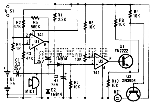
In the circuit, U1 amplifies the audio captured by the condenser microphone. Resistor R1 limits the current, while R2 and R3 center the amplifier's output to a voltage level of %B+ to facilitate the use of a single-ended power...
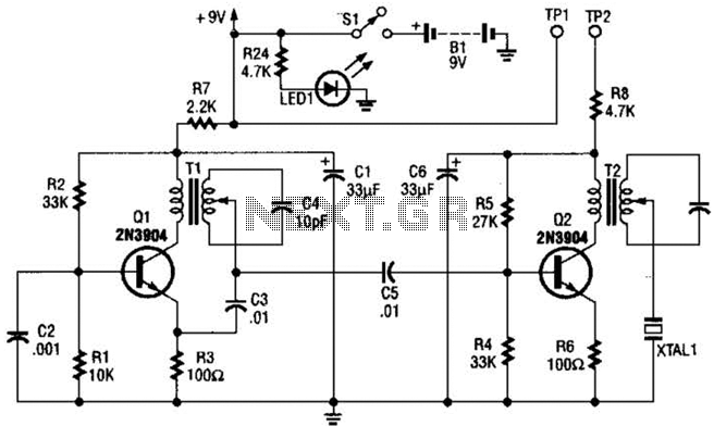
The transmitter features a VXO circuit that drives a keyed amplifier. This keyed amplifier powers an MRF 476 final amplifier, producing approximately 2 watts of output. Additionally, a solid-state T-R switch is incorporated for the receiver. The component values...
Warning: include(partials/cookie-banner.php): Failed to open stream: Permission denied in /var/www/html/nextgr/view-circuit.php on line 713
Warning: include(): Failed opening 'partials/cookie-banner.php' for inclusion (include_path='.:/usr/share/php') in /var/www/html/nextgr/view-circuit.php on line 713