
how to make automatic vehicle headlight
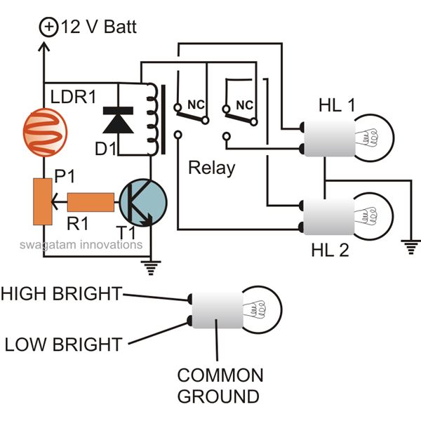
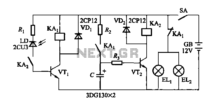
The automatic headlamp dipper circuit utilizes a light-dependent resistor (LDR) as a key component to detect incoming light. The LDR's resistance decreases when exposed to bright light, such as that from oncoming vehicle headlights. This change in resistance is crucial for the operation of the circuit. The transistor, functioning as a comparator, is connected to both the LDR and a preset resistor. When the LDR detects light, its resistance drops, which in turn increases the current flowing to the base of the transistor. The transistor, once activated, allows current to flow through its collector-emitter path, energizing the relay.
The relay serves as an electromechanical switch that controls the headlamp intensity. When the relay is activated, it changes the connection of the headlamps from the main filament to the dimmer filament, effectively "dipping" the headlights. This automatic adjustment helps prevent glare for oncoming drivers and enhances safety by allowing the driver to maintain focus on the road without the distraction of manual adjustments.
The circuit should be carefully designed to ensure that the LDR is positioned in a location that accurately represents the lighting conditions experienced by the driver. Proper enclosure of the circuit components is essential to protect against environmental factors, while ensuring that the LDR remains exposed to light sources. This design not only improves convenience for the driver but also contributes to safer driving practices during nighttime conditions. The implementation of such an automatic headlamp dimmer circuit can significantly enhance the driving experience by reducing the cognitive load on the driver, allowing for a more focused and safer journey.The circuitdescribed herecan be built and used in your vehicle for an automatic dipping and dimming operation of the headlamps, in response to the intense lights coming from an opposite vehicle headlamps. You must have come across this irritating situation while driving at night when you find the headlight focus from an opposite vehicle fallin
g straight in your eyes, making things difficult to assess, giving rise to a situation of a collision or some kind of possible accident. Such situations are normally tackled by using manual dipper switch mechanism, where the driver is prompted to "dip" the focus of his headlight, thus giving the opposite vehicle a chance to adjust his vehicle and also an indication that he too needs to "dip" his vehicle lamps.
However, doing the above operation manually, every now and then can become horribly laborious and troublesome, therefore if some kind of automatic system is Incorporated, can help to save this headache of the driver, especially while he is driving in stressful conditions and on dangerous highways. The following diagram describes a simple yet effective auto head lamp dipper or dimmer circuit. The transistor is used as a comparator, which compares the preset resistance level and the LDR resistance level with reference to ground.
Light falling over the LDR from the headlight of the vehicle coming from the front instantly lowers its resistance and allows more current to flow to the base of the transistor. The transistor conducts and activates the relay, which in turn flips the contacts such that the host vehicle`s headlamps gets connected with the dipper filament, changing its intensity.
The whole circuit may be enclosed in a small box and installed somewhere near the driver`s dashboard area, however the LDR needs to be wired and placed out of the enclosure, in some corner of the wind shield, so that it is able to "see` the light from the opposite vehicles just as the driver would see them. 🔗 External reference
Related Circuits
The article presents a circuit concept that features an innovative method for detecting minimal shocks caused by potential earthquake tremors. This circuit is highly sensitive, capable of detecting tremors of magnitude 4 on the Richter scale, while remaining unaffected...
Nowadays, a switch-off delay for vehicle interior lighting is a standard feature. However, certain models with minimal settings or older vehicles leave users in the dark as soon as they enter and close the door. This situation calls for...
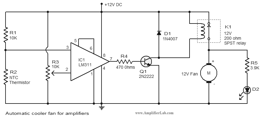
An automatic cooler fan for amplifiers is a circuit designed to conserve power in amplifier circuits. This circuit activates the fan. The automatic cooler fan circuit for amplifiers operates by utilizing temperature sensors to monitor the heat generated by the...
When driving at night and approaching another vehicle, traffic regulations dictate that the distance between the two vehicles should be maintained. This is achieved by alternately activating and deactivating the high beams, while utilizing either the wide lights or...
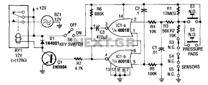
In this circuit, IC1A and IC1B serve as a monostable multivibrator. Any input from the sensors SI through S5 triggers IC1A to produce a logic low signal, which activates IC1B, turning on Q1 until the capacitor C3 discharges through...
This mini logic analyzer is a tool that allows users to observe the logic transitions (0 or 1) of a digital data signal on an LCD display. Such digital data signals can be found on the output pin of...