
Automatic telephone recording circuit
The audio signal is transmitted through the attenuator resistor R1 and DC isolating capacitors C1 and C2. The device functions as a high-impedance switch that isolates the recording device from the phone line using relatively simple electronic circuitry. It requires no battery, as it derives its operating power from the remote jack, which typically provides 6 volts in most recorders. When clamped to ground, it initiates the operation of the recorder. The unit is compatible with most portable cassette recorders, provided they are equipped with a remote control jack.
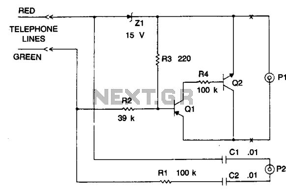
The schematic of this device includes several key components that work together to achieve the desired functionality. The core of the circuit is formed by transistors Q1 and Q2, which are configured to operate as switches. Resistor R3 is critical for maintaining the forward bias on Q1, ensuring that the circuit remains active under normal conditions. Resistor R4 is used to ensure that Q2 remains in a saturated state, thus allowing for efficient switching.
The Zener diode D1 plays a crucial role in controlling the switch's operation. When a negative voltage is applied, it effectively overrides the forward bias created by R3, turning off the switch. This feature is essential for preventing unwanted recording when the phone is not in use. The transition from the on-hook state (48 volts) to the off-hook state (10 volts) is managed by the inherent properties of the Zener diode, which allows for a smooth operation of the switch.
The audio path includes attenuator resistor R1, which is designed to limit the signal level to prevent distortion during recording. Capacitors C1 and C2 serve as DC isolation components, allowing the audio signal to pass while blocking any DC voltage that could interfere with the recording process. This configuration ensures that the recording device receives a clean audio signal without any DC offset, enhancing the quality of the recorded material.
Overall, this circuit is designed to be simple yet effective, providing a reliable means of interfacing between a phone line and a recording device without the need for additional power sources. Its compatibility with various portable cassette recorders makes it a versatile solution for audio recording applications.The device is a dc switch that is normally on via the forward biasing of Ql via R3. Ql now clamps Q2 into a forward state by biasing its complement well into a saturated state via R4. The dc switch is turned off via a negative voltage above that of the zener (Dl). This voltage is usually about 48 and is the on-hook value of the phone line. This negative voltage overrides the effect of R3 and keeps the circuit "off." When the phone is off the hook, the 48 volts drops to 10 volts, that is below the zener voltage of Dl and R3 now turns the circuit on. The audio signal is via attenuator resistor Rl and dc isolating capacitors Cl, C2. The device is a high impedance switch that isolates the recording controlled device from the phone line via some relatively simple electronic circuitry. It requires no battery and obtains power for operating via the remote jack that in most recorders is a source of 6 volts.
When clamped to ground it initiates recorder operation. The unit interfaces with most portable cassette recorders providing they contain a remote control jack. 🔗 External reference
Related Circuits
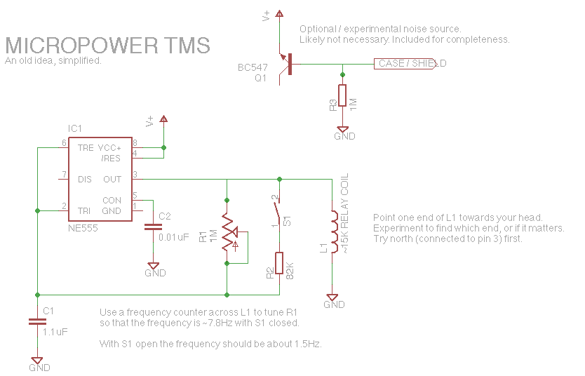
Let's face it, not every day is the greatest. Sometimes, one may not feel like doing much of anything. Wouldn't it be nice if there was a way to change brain waves at the push of a button? Transcranial...
This audio noise filter circuit functions as a bandpass filter specifically designed for the audio frequency range. It effectively filters out unwanted signals that fall below or above the desired audio frequencies. The circuit comprises two filters: a low-pass...
This solid-state push-pull single-ended Class A circuit is designed to deliver sound quality comparable to valve amplifiers, providing an output power of 6.9W measured across an 8 Ohm loudspeaker cabinet load. It features reduced total harmonic distortion (THD), increased...
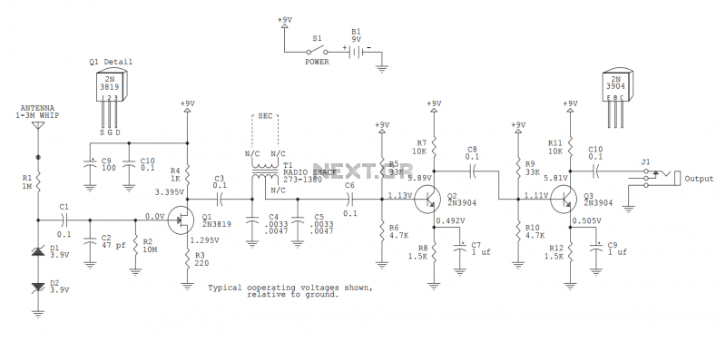
This version sports a 2nd audio amplifier stage at Q3. The output level with this version is sufficient to drive a crystal headphone to a comfortable volume. The "crystal" headphone is like those used on ye olde crystal radios....
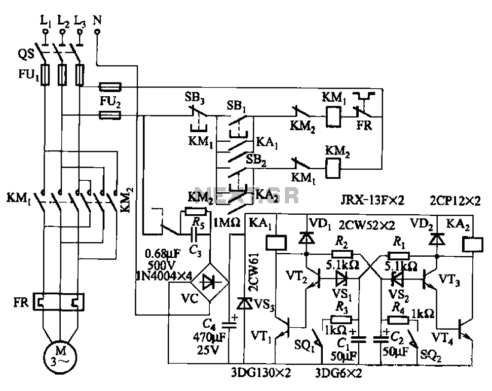
The circuit illustrated in Figure 3-72 employs a deformable bistable reversing motor control mechanism that automatically initiates and halts operation during a user-defined time delay. This feature is designed to safeguard the motor from potential impacts during the reversing...
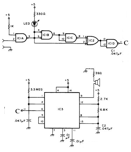
The NE556 timer can function as an indicator for the static state of a digital logic audible terminal. An audible logic probe is beneficial for visually inspecting a component while simultaneously checking the logic state at another point far...
Warning: include(partials/cookie-banner.php): Failed to open stream: Permission denied in /var/www/html/nextgr/view-circuit.php on line 713
Warning: include(): Failed opening 'partials/cookie-banner.php' for inclusion (include_path='.:/usr/share/php') in /var/www/html/nextgr/view-circuit.php on line 713