
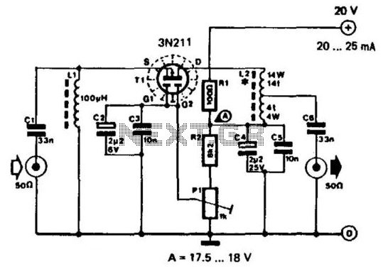
5 Watt Class-A Audio Amplifier Circuit diagram
This circuit employs a solid-state design that mimics the characteristics of traditional valve amplifiers while overcoming some of their limitations. The push-pull configuration enhances efficiency and reduces distortion, making it suitable for high-fidelity audio applications. The output stage consists of two transistors (Q2 and Q3) that work in tandem to drive the load, allowing for higher output power while maintaining sound quality.
The choice of a 24V power supply facilitates a compact design, significantly reducing the physical size and complexity associated with high-voltage valve amplifiers. The lower operating voltage also contributes to enhanced safety and ease of integration into various audio systems.
The circuit's performance can be fine-tuned by adjusting R8 to ensure the current draw remains at 700mA, thus optimizing the power consumption and thermal management of the system. The inclusion of a large heatsink for Q2 and Q3 is essential to dissipate heat effectively, preventing thermal overload and ensuring reliability during prolonged operation.
Additionally, the optional bass-boost feature, implemented through R5 and C5, provides users with the ability to enhance low-frequency response, catering to different listening preferences and acoustic environments. This feature can be particularly beneficial in applications where bass response is critical, such as in home theater systems or music production setups.
Overall, this solid-state push-pull single-ended Class A circuit represents a modern approach to audio amplification, combining the warmth and character of valve amplifiers with the advantages of solid-state technology.This solid-state push-pull single-ended Class A circuit is capable of providing a sound comparable to those valve amplifiers, delivering more output power (6. 9W measured across a 8 Ohm loudspeaker cabinet load), less THD, higher input sensitivity and better linearity.
Voltage and current required for this circuit are 24V and 700mA respectively, co mpared to 250V HT rail and 1A @ 6. 3V filament heating for valve-operated amplifiers. The only penalty for the transistor operated circuit is the necessity of using a rather large Heatsink for Q2 and Q3 (compared to the maximum power delivered). In any case, the amount of heat generated by this circuit can be comparable to that of a one-valve amplifier.
An optional bass-boost facility can be added, by means of R5 and C5. Total current drawing of the circuit, best measured by inserting the probes of an Avo-meter across the positive output of the power supply and the positive rail input of the amplifier, must be 700mA. Adjust R8 to obtain this value if necessary. 🔗 External reference
Related Circuits
This RF amplifier features a wide bandwidth and dynamic range. It provides a gain of 10 dB, with a noise figure of less than 5 dB. The third-order intercept point (IP3) is -40 dB at an output of +22...
If a negative supply is required for an operational amplifier or if a negative bias voltage is needed while operating from a single supply voltage, such as in battery applications. To generate a negative supply voltage from a single positive...
This project will explain how I build my new wattmeter. This watt meter will be able to measure power from 300nW to 30W @ (0-500MHz). This wattmeter is based up on a dummy load of 50 ohm which can...
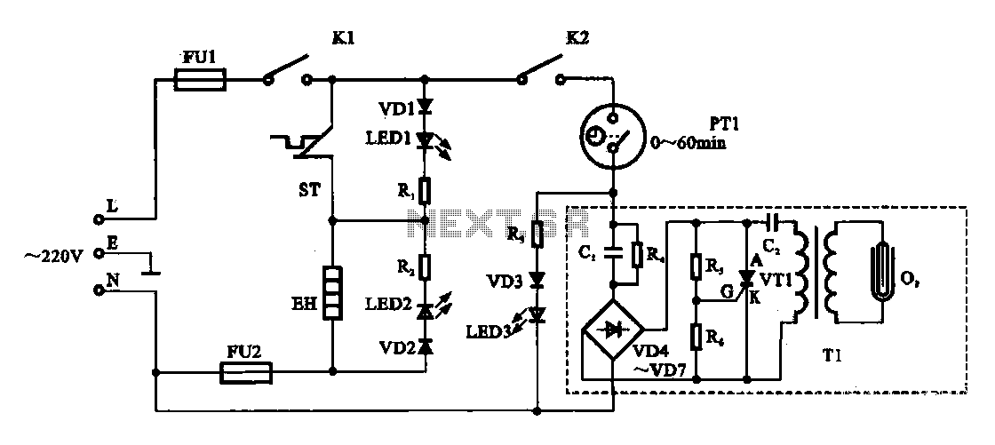
The dispenser (Aucma) temperature detection control circuit is designed to manage the temperature of the dispenser. It consists of two primary components: a heating control circuit and a fresh cabinet control circuit that provides power to an ozone generator....
The circuit exhibits a flat frequency response ranging from approximately 20Hz to over 50kHz. The input sensitivity is set at 100mV for full-scale deflection on a 100µA meter. It is constructed using two common emitter amplifiers; the first stage...
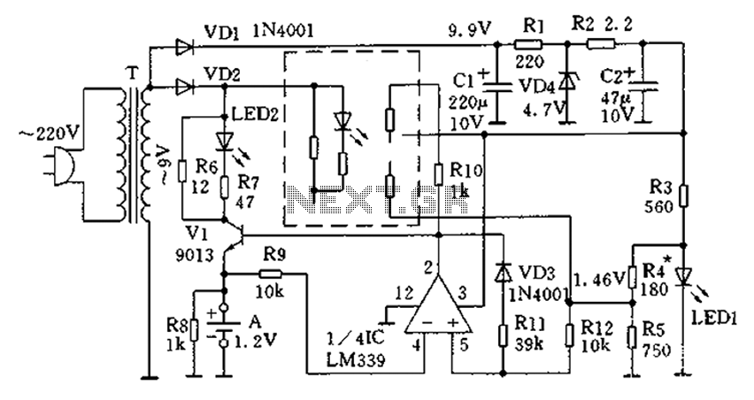
The circuit operates for 10 hours using constant current charging, providing convenience. The electricity from the secondary transformer T is stepped down, with the output directed through VD1 for rectification, followed by R1 and C1 for filtering. VD4 regulates...
Warning: include(partials/cookie-banner.php): Failed to open stream: Permission denied in /var/www/html/nextgr/view-circuit.php on line 713
Warning: include(): Failed opening 'partials/cookie-banner.php' for inclusion (include_path='.:/usr/share/php') in /var/www/html/nextgr/view-circuit.php on line 713