
Automatic UPS system wiring circuit diagram for Home or Office (New Design With One Live Wire)

The described circuit involves a configuration where both the phase and neutral wires are initially connected from the power source to various electrical appliances. The integration of a UPS (Uninterruptible Power Supply) into this circuit allows for seamless transition between the main power supply and battery backup during power outages.
In this setup, the UPS is responsible for charging the batteries while simultaneously supplying power to the appliances. The phase wire from the UPS is connected to the same point as the phase wire from the power source, ensuring that appliances receive power from either the UPS or the main supply as needed. The neutral wire remains connected to the appliances, allowing for the completion of the circuit.
When the main power supply is active, the UPS remains in standby mode, and the appliances draw power directly from the main source. However, in the event of a power outage, the UPS automatically switches to battery power, allowing the appliances to continue operating without interruption. It is crucial to note that the second phase wire connected after the UPS installation remains inactive during normal operation, as the UPS is not drawing power from the batteries until the main supply fails.
The design ensures that the stored electrical energy in the batteries is utilized effectively when the main power supply is unavailable. This configuration enhances the reliability of the electrical system, providing continuous power to essential appliances while maintaining safety and efficiency. Proper installation and adherence to electrical codes are essential to ensure the system operates as intended and to prevent potential hazards.We had already connected Phase & Neutral (from Power house) to Electrical Appliances i. e. Fans, Light points etc. So according the above UPS Connection Diagram. connect an extra wire (phase) to those appliances where we have already connected phase and neutral from (from Power house) (i. e. , two wire as phase with same point). So no need to connect Neutral from UPS as it is already connected. Then Supply will continue through Phase wire (Note that Neutral is already connected) which is given to UPS from main board (it will charge your battery as well). and then from UPS to Electrical Appliances. So the Second one phase which is connected after UPS installation (i. e. One Live Wire from UPS) would be inactive because power supply is not available from UPS and batteries (Because it is Automatic UPS System).
then Supply will continue through Phase wire (Output UPS) which is Connected from batteries and UPS to Appliances (Note that Neutral is already connected). So the first one phase which is connected before UPS installation (i. e. Live Wire from Main board to UPS) would be inactive because power supply is not available from power house.
In this case, you consume the store Electrical energy in the batteries. 🔗 External reference
Related Circuits
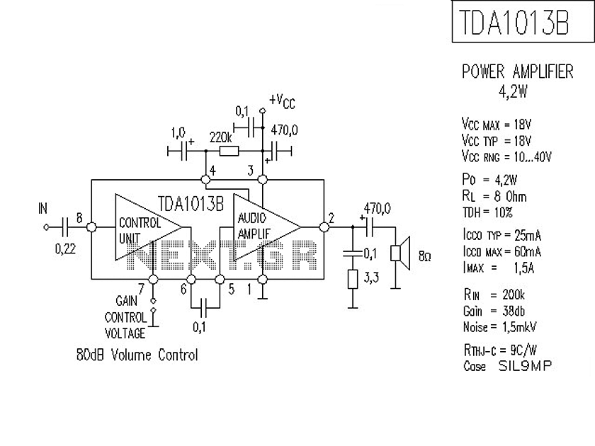
The following is a circuit for a 4-watt audio amplifier. The amplifier utilizes an integrated audio amplifier chip, TDA1013B, which is capable of delivering an audio power output of up to 4W at an 8-ohm load. Its wide supply...
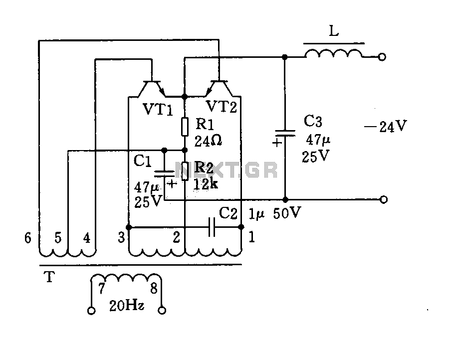
The circuit described is a 20Hz signal generator suitable for telephone ringing systems, alarm systems, and various other electronic applications. It consists of a transformer (T) and two transistors (VT1 and VT2), forming a push-pull oscillator. The two transistors...
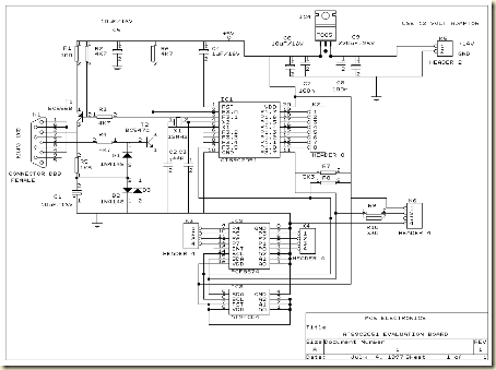
The circuit is better referred to as the Evaluation Board for the AT89C2051 and AT89C4051 microcontrollers. This Minimum System Evaluation Board for the AT89C2051 and AT89C4051 offers several advantages in terms of hardware support. The Evaluation Board for the AT89C2051...
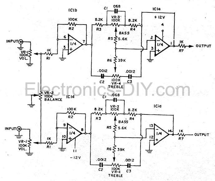
This simple tone control (bass and treble control) can be utilized in various audio applications. It can be integrated into amplifiers, function as a standalone control module, or even be incorporated into new and innovative instruments. The circuit employs...
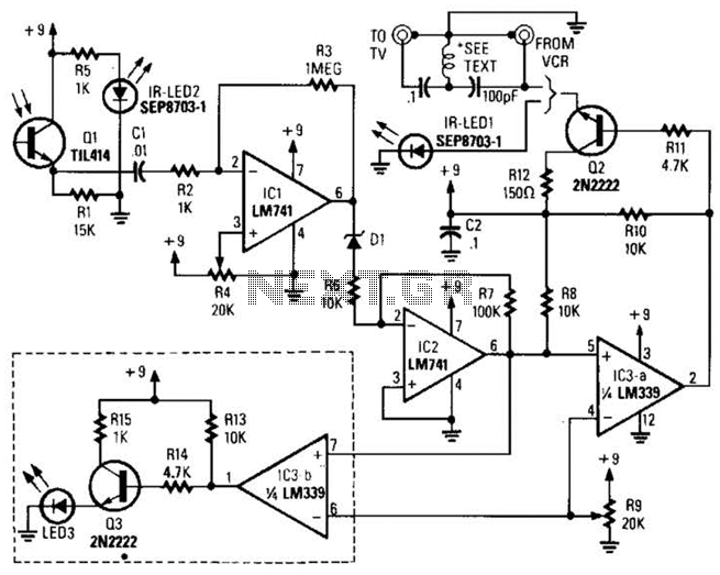
A signal from an infrared (IR) remote control is converted from IR radiation to a frequency pulse that can be transmitted through coaxial TV cable or any other two-conductor wire to another room, where it is converted back into...
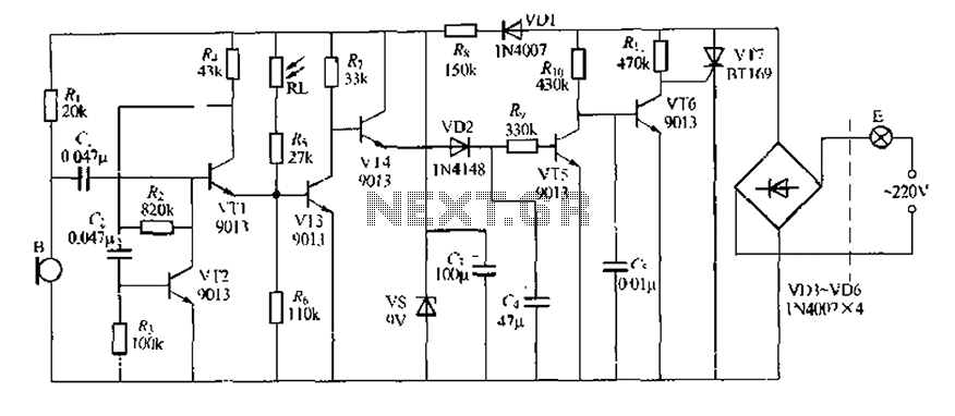
This circuit design is a sound and light control delay switch for staircase walkway lighting, featuring high voice sensitivity. In the evening, when someone walks on the stairs, their footsteps activate the electronic meter, turning on the lights. If...
Warning: include(partials/cookie-banner.php): Failed to open stream: Permission denied in /var/www/html/nextgr/view-circuit.php on line 713
Warning: include(): Failed opening 'partials/cookie-banner.php' for inclusion (include_path='.:/usr/share/php') in /var/www/html/nextgr/view-circuit.php on line 713