
20Hz signal generator (phone-ringing) circuit diagram
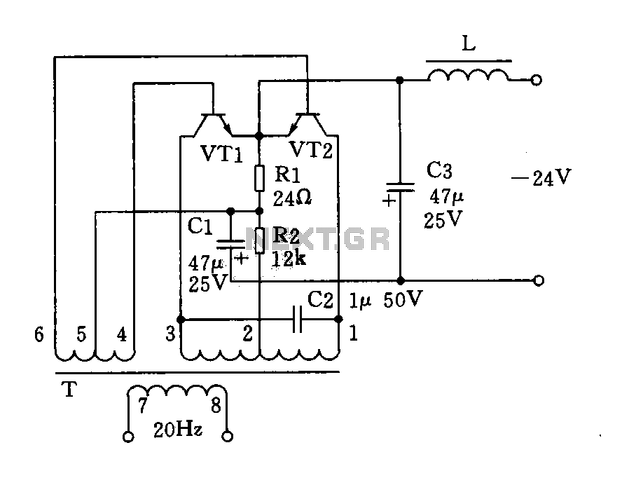
Component selection includes transistors VT1 and VT2, specifically the 3DD4E model, with parameters ranging from 30 to 80. The radiator area is specified as 100 mm², made from aluminum with a thickness of 2 mm. The oscillation transformer (T) is constructed from E-type silicon material with a core cross-sectional area of 35 mm² x 22 mm². The windings consist of various gauges of high-strength wire: L1 to L3 uses 0.49 mm wire wound with 189 turns; L4 to L6 uses 0.25 mm wire wound with 40 turns, with taps around the center; and L7 to L8 uses 0.35 mm wire wound with 60 turns. The choke coil (L) is also made from E-type silicon material with a core cross-sectional area of 20 mm² x 15 mm², utilizing 0.55 mm wire wound with 800 turns. Resistors are selected as 1/2W metal film types. Other component values are indicated in the provided schematic, with no special requirements.
The 20Hz signal generator circuit is designed for versatility in various electronic applications, particularly in telephone and alarm systems. The push-pull oscillator configuration enhances efficiency by allowing the transistors to work alternately, minimizing power loss and maximizing output. The choice of transistors, specifically the 3DD4E model, ensures that the circuit operates within optimal parameters for both frequency and power consumption.
The transformer plays a crucial role in this circuit, with its E-type silicon core providing effective magnetic coupling necessary for the oscillation process. The specified winding configurations and wire gauges are critical for achieving the desired inductance and ensuring stable operation. The use of high-strength wire materials contributes to the durability and reliability of the circuit, which is essential for applications in alarm systems where consistent performance is paramount.
The radiator's dimensions and material selection are also important, as they facilitate the dissipation of heat generated during operation, ensuring that the transistors remain within safe temperature limits. The use of metal film resistors enhances the circuit's performance by providing accurate resistance values and improved thermal stability.
Overall, this circuit design combines careful component selection and configuration to create a reliable, efficient signal generator suitable for a range of electronic applications. The detailed specifications provided ensure that engineers can replicate or modify the design to meet specific requirements in their projects.As shown for the 20Hz signal generator, may be applied to the telephone ringing system, the signal source can also be used for alarm systems and other electronic Used. The circuit is actually a transformer T and a transistor VTl, VT2 composition of total fat push-pull oscillator, two transistors working in the off state (saturation and cut-off), the output waveform is a square wave. Transistor low power consumption and high efficiency.Component selection: transistor VTl, VT2: 3DD4E, = 30 ~ 80 (parameter selection as consistent).
Radiator area l00 50mm2, aluminum plate having a thickness of 2mm. Oscillation transformer T: using E-type silicon material, core cross-sectional area of 35 22mm2. Ll-3: µ0.49mm high strength wire, wound 189 turns. L4-6: µ0.25mm high strength wire, wound 40 turns, and all around the center wire taps. L7-8: µ0.35mm high strength wire, wound 60 turns. Choke coil L: using E-type silicon material, core cross-sectional area of 20 15mm2. L: µ0.55mm high strength wire, wound 800 turns. Resistor nominal power are selected 1 / 2W metal film resistors. Other component values as shown in the figure, no special requirements.
Related Circuits

This is a simple transmitter circuit diagram that offers decent coverage. The circuit can operate with a power supply of 9-12V. To tune this circuit... This simple transmitter circuit is designed to provide reliable performance within the specified voltage range....
This circuit employs a phototransistor along with four operational amplifiers to function as a total energy detector. It is designed to measure the total energy of optical pulses transmitted through an optical cable communication system. When the light intensity...
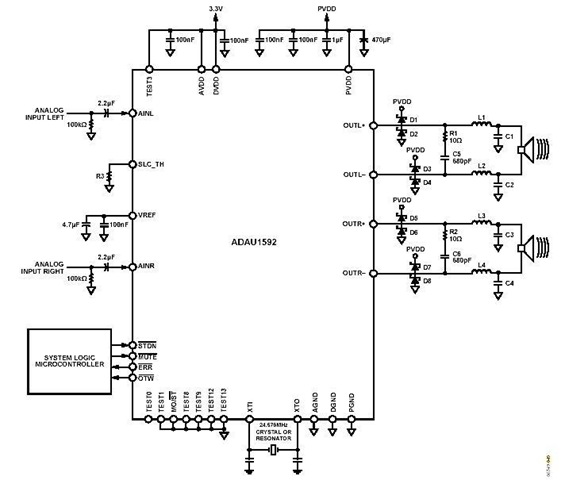
This is a stereo circuit schematic of the ADAU1592, a 2-channel, bridge-tied load (BTL) switching audio power amplifier. The ADAU1592 can be utilized in compact television sets, PC audio systems, and mini-component applications. According to the ADAU1592 datasheet, an...

This is a door knob touch alarm designed for home security purposes. The alarm will activate when someone touches the metal door knob. This circuit will not function on a fully metal door. Currently, circular batteries are used, but...

Starting a fluorescent lamp on an inverter can be challenging due to the trade-offs involved in achieving optimal operating efficiency with 12V drivers. Fluorescent lamps require a specific starting voltage to ionize the gas within the tube and initiate the...
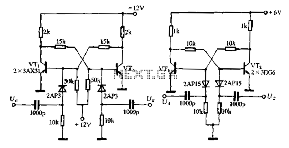
Bistable circuit operating at a frequency of 10 kHz or lower. A bistable circuit, also known as a flip-flop, is a fundamental building block in digital electronics. It has two stable states and can store one bit of data. The...