
Discrete components sound and light control stairs delay switch circuit 9
The circuit operates on a principle that utilizes sound detection to control the lighting of a staircase. The bridge rectifier formed by Vn3 to VD6 converts AC to DC, ensuring that the transistors receive a stable voltage. The use of a photoresistor allows the circuit to differentiate between day and night, effectively controlling the operation of the lighting system based on ambient light conditions.
The audio detection mechanism is critical to the functionality of this circuit. The electret condenser microphone picks up sound waves, converting them into electrical signals. These signals are then processed through the audio amplifier configuration formed by transistors VT1 and VT2. The feedback loop between these transistors ensures that even low-level audio signals can be amplified sufficiently to trigger the subsequent actions of the circuit.
When the microphone detects sound, it sends a signal that biases VT1, allowing it to conduct and subsequently drive VT3. This action leads to the conduction of VT4, which activates the light. The delay function is achieved through the RC timing circuit, where the capacitor C discharges through resistor R, controlling the time the light remains on after the last detected sound.
The design also incorporates safety features, such as the use of a thyristor (VT7) to manage the switching of the lamp, preventing accidental turn-on during undesired conditions. The choice of components, including the specific gain requirements for the transistors, ensures that the circuit maintains high sensitivity and reliability over time.
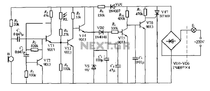
Overall, this sound and light control delay circuit is an innovative solution for enhancing safety and convenience in stairway lighting, demonstrating effective integration of audio detection, amplification, and light control technologies.A unique circuit design sound and light control delay stairs walkway lighting switch, it has a higher voice sensitivity. In the evening, when someone walking on the stairs r, f ootsteps will make the operation of the electronic meter off, lights electric light, people no sound that is left after 30s lamp will extinguish itself. Vn3 -VD6 form a bridge rectifier circuit, by R. Limiting buck, vs regulators, c m filtering lose about 9V DC voltage for transistors VT1-VT4 sheet j electricity.
RL daytime photoresistor resistance was low, VT3 conduction, VT4 off. In this case C. In particular on the voltage, VT: i deadline, VT6 conduction, VT7 thyristor gate and cathode are VT6 shorted. VT7 father off, lamp E does not shine. Night, RL light irradiation, showed a high resistance, but ran in biasing R makes VT1 conduction, VT1 emission catch eight VT3 base current flows, so VT3 still in a conducting state, so in a quiet state, lamp It will still not be electrically lit.
J stairs when someone walking their footsteps or conversation after picking microphone B, m corresponding to the input signals Yi to the VI] zoom. After the release of the audio signal and the Yili Ding v 1 emitter VT3 injected into the base of the other aspects of the VT1 collector catch output by C.
Coupled to the base VT2, VT2 signal by amplifying its lake collector output m away again to shake VT1 base. Thus called See, VT1 and VT2 composition TF feedback audio amplifier, it has a very high gain of the circuit, the circuit thus has a high voice sensitivity, this is the clever design of the circuit lies.
Since V T3 group has a strong pull audio signal input, the negative half cycle of the signal makes its exit VT3 conduction state, state and even zoom into the off state. VT3 collector electric ft rise. vr4 conduction, 9V DC voltage by VT4, VD2 to (rapid charge, and so by R. T5 is turned on, VTfi off, lift the VT7 thyristor gate closure gate lock .V T7 by the R-, obtained only to trigger current, VT7 opened, lamp E on the light-emitting electric lamp is lit, the light itself into a low resistance although so R1J make VT3 conduction blockade, but because C.
has full charge, C, by R. to VT5 emitter discharge, VT5 still maintain an on-state, so the lights continue beetle bright rug. f when discharged, VT5 off, VT6 conduction, VT7 off, lights off as Tiao have sound again, women fork electric energy lighting delay circuit when IHj abundance determined by R., G discharge time constant, the icon data about 3.s. white days, because VT3 blockade, then a loud noise it will never lamp lighting. WRI, VT:/requirements magnification p values greater than 200. the other transistor p value of about 100 is appropriate. VT5, VT6 of pVceo require some as high as possible electret condenser microphone B best selection of better stability.
with white spots the subject of the kind of package. other components shown in Figure parameters, no special requirements.
Related Circuits

The ATR0981 is a monolithic integrated circuit (IC) produced using Atmel's advanced SiGe technology. This IC serves as a transmit and receive front-end solution, specifically designed for operation within a frequency range of 300 MHz to 500 MHz. It...

The project described in this article is a constant Q, fully expandable graphic equaliser. Where most "conventional" graphic EQ circuits have a Q that is dependent on the setting of the pot, this one maintains the same Q at...

The 2N5485, which has a very low-capacity legacy, is always operated as a source follower with gate bias bootstrap. In this circuit, nothing is left to chance in reducing input capacitance. The 2N5485 is a JFET (Junction Field Effect Transistor)...

The Smart Ballast IC is designed to control a fluorescent lamp ballast, including a Discontinuous Conduction Mode Power Factor Correction (PFC), lamp inverter control, and a high voltage level shift half-bridge driver. The application requires a minimum number of...
Colour sensor is an interesting project for hobbyists. The circuit can sense eight colours, i.e. blue, green and red (primary colours); magenta, yellow and cyan (secondary colours); and black and white. The circuit is based on the fundamentals of...
The wireless FM transmitter circuit described here includes an additional RF power amplifier stage following the oscillator stage, which increases the power output to 200-250 mW. The wireless FM transmitter circuit functions by modulating audio signals onto a radio frequency...