
Automatic White-LED Garden Light
The circuit operates efficiently in a self-sustaining manner, leveraging the solar cell's energy to power the LED during nighttime conditions. The use of a NiCad battery ensures reliable performance, even in low-light conditions. The diode D1 is crucial for preventing backflow of current, thus protecting the solar cell and ensuring that the battery remains charged. The blocking oscillator configuration allows for effective energy transfer from the battery to the LED, while the feedback mechanism ensures that the LED is driven only when necessary, maximizing battery life.
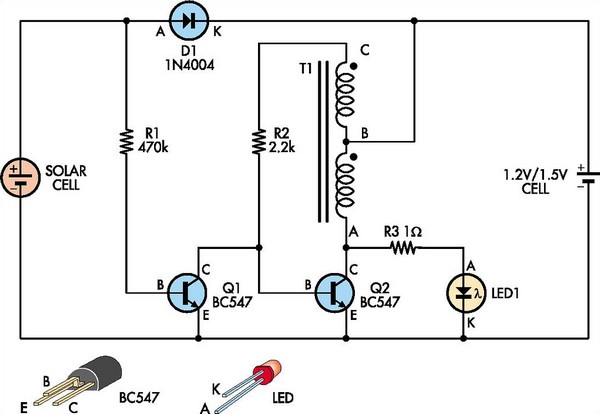
The design also incorporates flexibility in the choice of components, as demonstrated by the successful use of various cores and winding configurations. This adaptability allows for optimization based on available materials and desired performance characteristics. The circuit's simplicity and reliance on basic electronic components make it an excellent choice for DIY enthusiasts and educational projects, promoting an understanding of solar energy utilization in practical applications.This white-LED driver circuit is ideal for use in a garden light. It automatically turns the LED on at night and runs from a single 1. 2V nicad cell which is recharged by a solar cell during the day. The prototype used the existing casing and solar cell from an old garden light but you could also use a solar cell from a solar education kit. Diode D 1 allows the solar cell to charge the battery during the day and prevents it from discharging back into the solar cell at night. Transistor Q1 controls the LED driver circuit. This transistor is normally on during the day (ie, when there is output from the solar cell) and so Q2 and the LED are off.
At night time, Q1 is off and this allows a simple blocking oscillator circuit based on T1, R2 and Q2 to operate. This circuit in turn drives LED1 via a 1W resistor which limits the peak current into the LED. T1 is wound bifilar, with the two windings configured to produce a center-tapped winding. Winding AB is the main primary winding and winding BC is the feedback winding. The number of turns and the core used are not critical. The prototype worked with a toroid scrounged from an old computer power supply, as well as with a small ferrite suppression bead and an Altronics L5110 core.
The toroids were wound using 10 turns of 0. 25mm wire, while the ferrite bead worked with just five turns of 0. 25 mm wire through the hole (that`s all that would fit). The oscillator works like this: when Q1 turns off, current flows through R2 and turns Q2 on. This causes current to flow through winding AB and the core produces a magnetic flux. And that in turn causes end C on the transformer to rise above the battery voltage and turn Q2 on hard. When the core saturates, the voltage at C drops back to the battery voltage, thus reducing the current in winding AB.
As this happens, the flux in the core starts to fall and this causes the voltage at C to drop below 0. 6V. As a result, Q2 turns off and because there is now no current in AB, the flux in the core starts to collapse.
What happens now is that the voltage on end A of the windings rises above the battery voltage. When it gets to 3. 2-3. 6V with respect to ground, LED1 "fires" and current flows from the battery via BA, through the LED and back to the battery. When the flux is spent, LED1 turns off and end C returns to the battery voltage. Current now flows through R2 and into the base of Q2 and the whole cycle starts over again. Finally, when the Sun rises the following morning, Q1 turns on, robs Q2 of its base drive, the oscillation stops and LED1 goes out.
🔗 External reference
Related Circuits
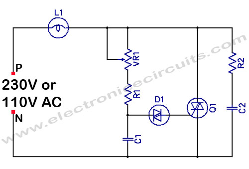
Filament Light Dimmer Circuit. This simple triac dimmer can be used to control incandescent filament lamps up to 200W. The circuit operates on standard AC voltage. The filament light dimmer circuit utilizes a TRIAC to control the power delivered to...
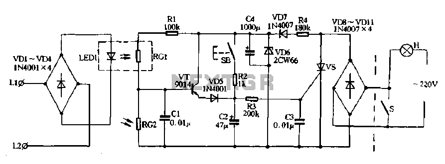
Diodes VD8 to VDI1 function as part of the main circuit isolation, with SCR serving as a composition control switch. The buck regulator circuit is composed of a stable orbital tube VD6 and a simple resistor-capacitor combination (C4). The...
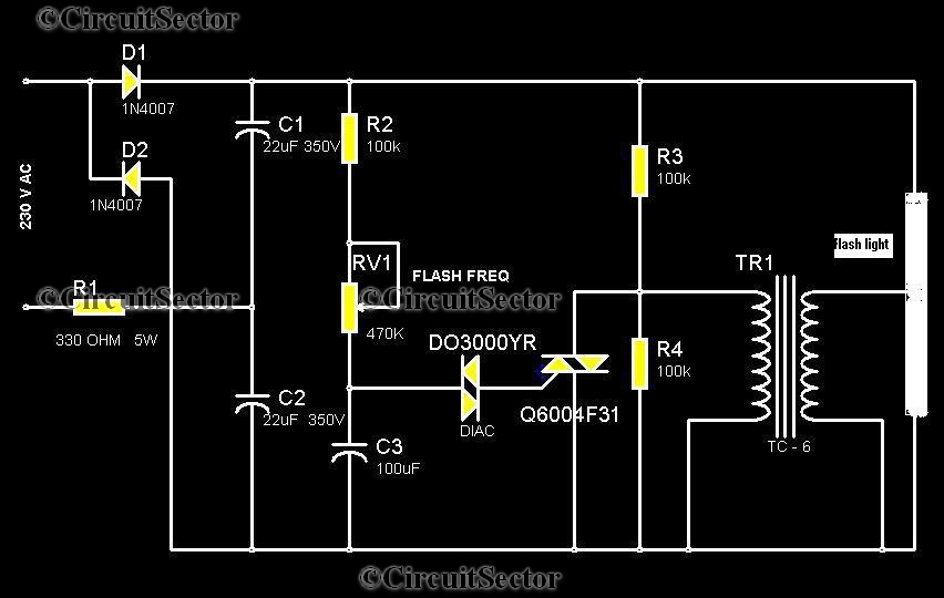
This circuit is a strobe light that allows for adjustable flashing rates. It utilizes a flash tube commonly found in cameras. In standard cameras, the flash may take ten to twenty seconds to recharge. However, this circuit enables the...
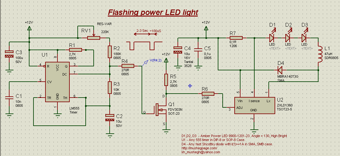
This project demonstrates the construction of a simple flashing light circuit using the IC 555 timer. The 555 timer functions as a clock generator with a duty cycle of less than 100% and greater than 50%. Additional components include...
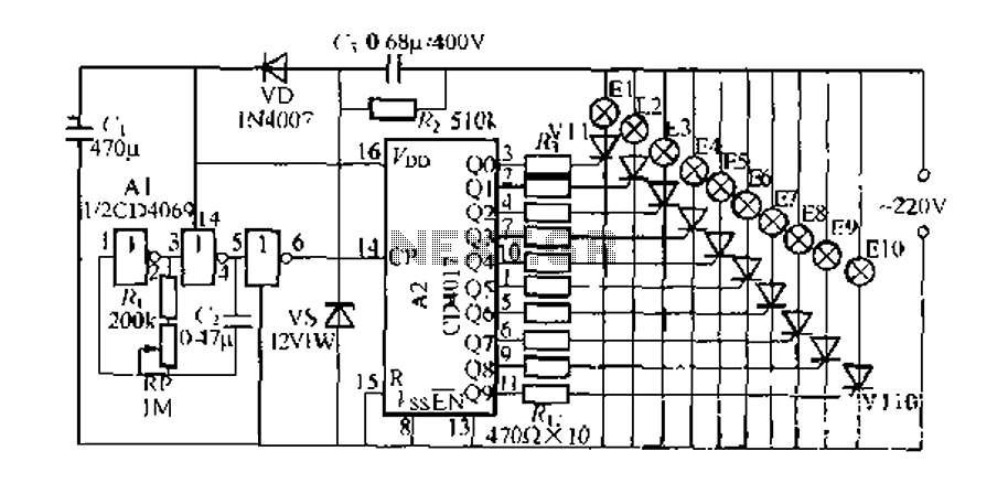
The digital integrated circuit consists of a controller for a string of ten road flashing lights, which drives the El-El0 string lights in a flashing cycle. The system utilizes a ten-count decoder, specifically the CD4017 digital integrated circuit. When...
The 741 operational amplifier is configured as an audio oscillator utilizing Radio Shack 276-677 photocells within the feedback circuit. When light illuminates PC1, its resistance diminishes, leading to a corresponding decrease in the frequency of the audio tone heard...