
Automatic lighting control telephone signals

The circuit described is a sophisticated implementation of a telephone light control system that integrates various components to achieve efficient operation. The use of diodes for isolation ensures that the control circuit remains unaffected by the main power line fluctuations. The buck regulator design, utilizing a stable orbital tube and RC components, facilitates a reliable DC output for the power control needs of the system.
The optocoupler configuration, utilizing LED1 and RG1, serves as an effective means of isolating the control logic from the high-voltage telephone line, ensuring safety and integrity of the components. The interaction between the light-emitting diode and the photoresistor plays a crucial role in determining the operational state of the circuit based on ambient light conditions, enhancing energy efficiency by preventing unnecessary power consumption during daylight.
The operational dynamics of the circuit are particularly noteworthy; the design ensures that the lamp remains off during the day while still being responsive to incoming calls. The charging and discharging behavior of capacitors C2 and C4, along with the SCR's control mechanism, allows for a delay in turning off the lamp after the call has ended, providing a visual indication that the phone was in use. This feature is particularly useful in scenarios where visibility is essential, such as in dimly lit environments.
Overall, the circuit is an exemplary model of integrating various electronic components to create a functional, energy-efficient light control system that responds intelligently to user interactions and environmental conditions.Diodes VD8 ~ VDI1, SCR vs composition control switch main circuit isolation diode VD7, stable orbital tube VD6, simple resistor capacitor C4 constitute buck regulator circuit, the output DC voltage of about 24V for power control circuit. Sensitive electrical resistors and light-emitting diodes LED1 RGl constitute an optocoupler, it photoresistor RG2 and i diode VT group into a phone, light control circuit. Ll, L2 side in series with the telephone line, usually when no call between L1, L2 no current flows through the light emitting diode LED] no light, so photoresistor RGI exhibit a high resistance, the transistor VT cutoff, controllable silicon vs also turned off, the lamp H does not shine.
At this time the entire circuit in a quiescent state, power consumption is minimal, less than found by ImA, can be considered not consume energy. When a telephone call is scored or off-hook dialing, between Ll, L2 current flows, the current telephone signal light-emitting diodes LED1 light, its light shines it presents a low resistance on the photosensitive resistor RGI.
If during the day, because by the treasury within RG2 natural light irradiation also showed low resistance, it (RGl + RI) partial pressure of lower voltage generated thereon, not enough to make VT conduction, so during the day, although the phone, lights not light. Only at night, RG2 showed high resistance, the above share a high voltage, so the transistor VT conduction, C4 charge stored on the adoption of VT, VD5 rapid charge to C2, C2 charged to about 20V so that the left and right voltage.
At the same time, C4 through the R3 vs SCR gate, between the cathode Yan electricity, so vs Xun said opening, electric lamp H lights up. Hang up after the call is finished, between L1, L2 no current flows through the transistor vT restore off, but the offer by R3 can continue to store charge in C2 vs gate current, so vs remain open state, L-what point lights remain bright light.
Be C2 discharge end, vs loss of trigger current, ie when the AC zero crossing Tuen off, lights off.
Related Circuits
This circuit generates an accurate and adjustable sine-wave output by removing harmonics from a square wave. This circuit utilizes a harmonic filter to transform a square wave input into a sine wave output. The primary function of this circuit is...
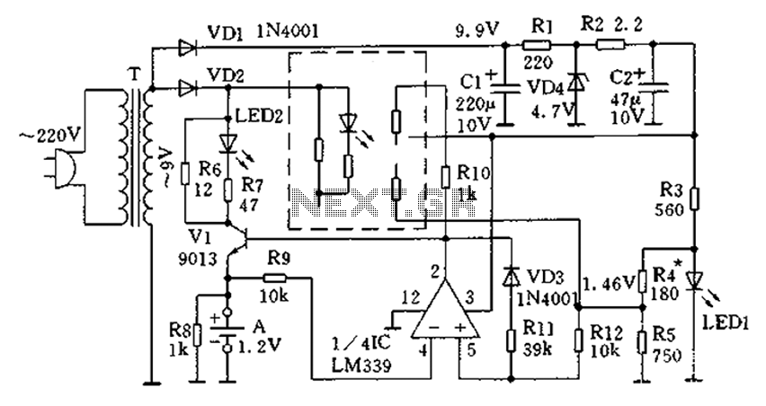
The circuit operates for 10 hours using constant current charging, providing convenience. The electricity from the secondary transformer T is stepped down, with the output directed through VD1 for rectification, followed by R1 and C1 for filtering. VD4 regulates...
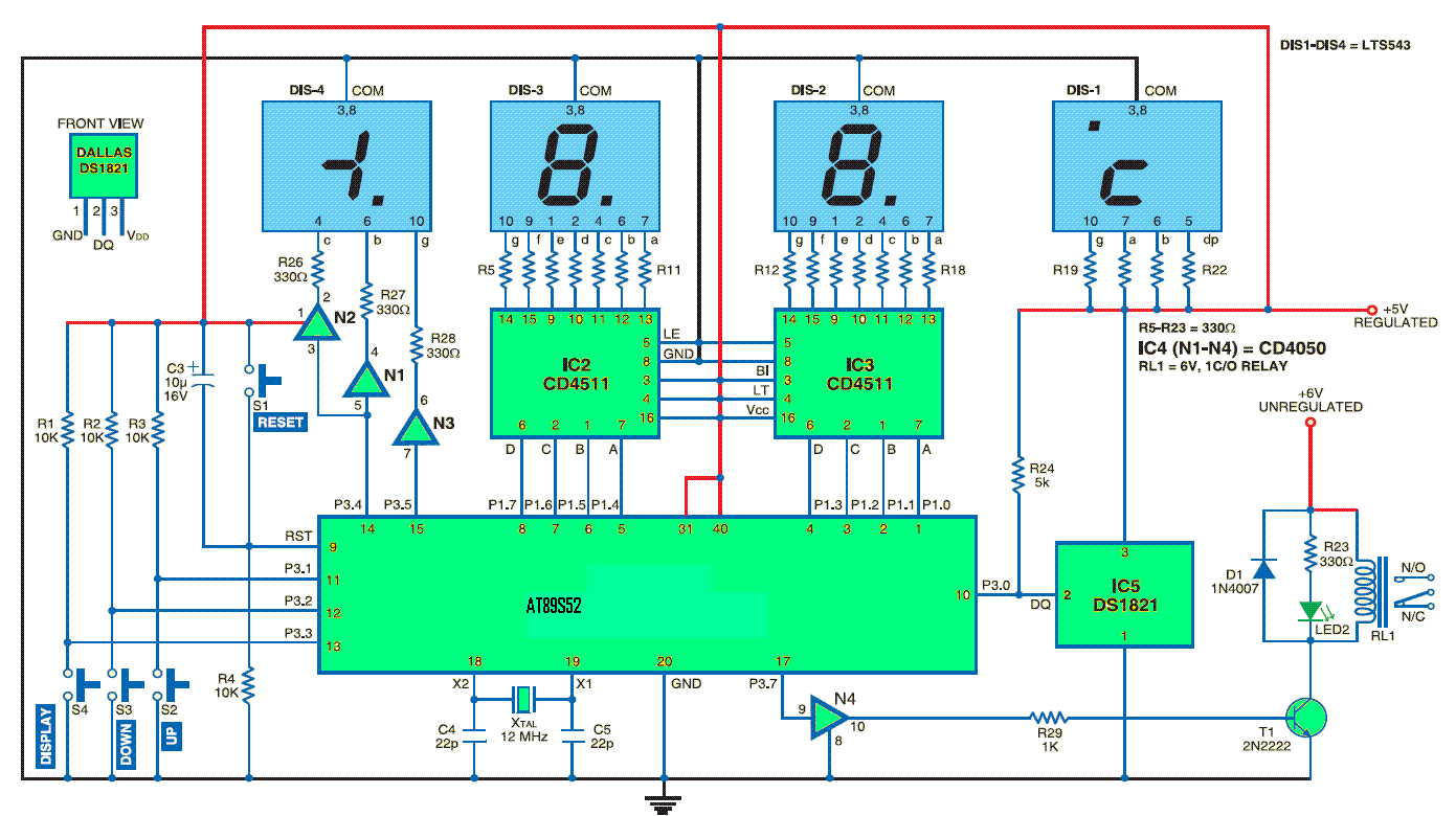
This standalone digital thermometer regulates the temperature of a device based on its requirements. It displays the temperature on four 7-segment displays, with a range from 55 to +125 °C. The core of the circuit is the AT89S52 microcontroller,...
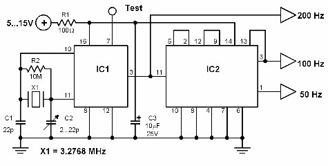
This circuit generates a 50 Hz timebase signal that is independent of the power line frequency. It is designed to provide the 50 Hz signal for electronic circuits that operate specifically with this clock frequency, primarily for circuits and...
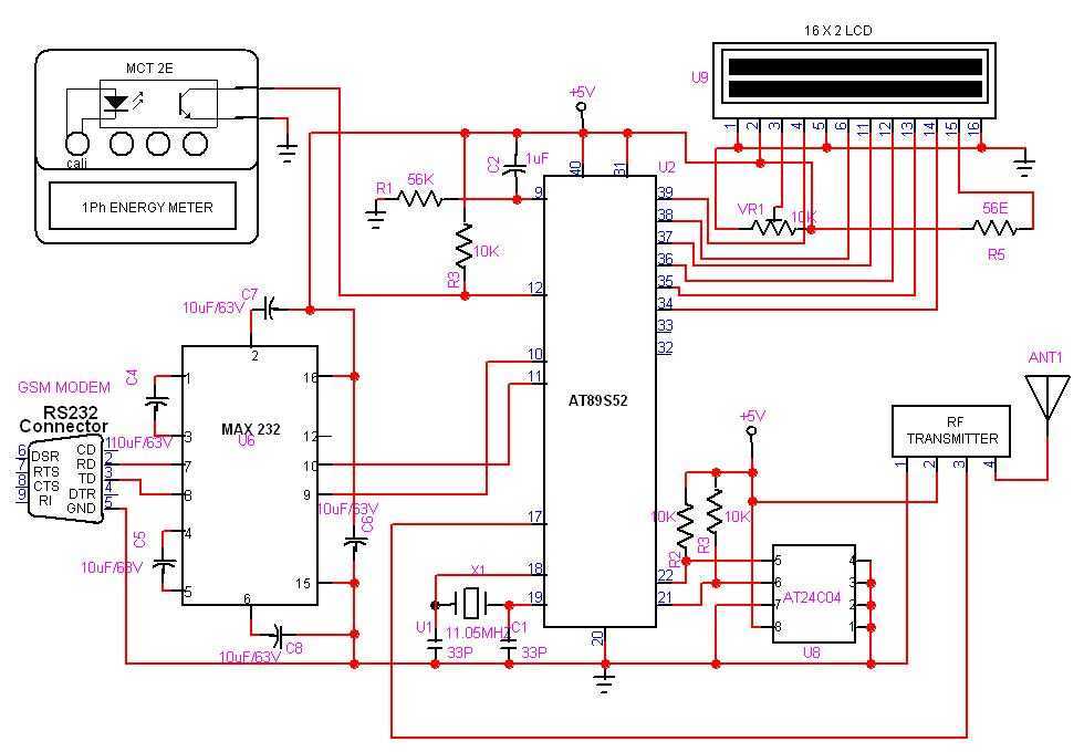
GSM based Automatic meter reading, or AMR, is the technology of automatically collecting data from energy meter and transferring that data to a central database for billing and/or analyzing. The Transmitter is connected to the meter and it counts...

A compact, inexpensive and low component count telecom headset can be constructed using two readily available transistors and a few other electronic components. This circuit is very useful for hands-free operation of EPABX and pager communication. Since the circuit...