
Automotive Buses and Vehicle Bus Description
The physical interface bus is crucial in automotive applications, enabling communication between various electronic control units (ECUs) and devices. The choice between optical and electrical interfaces affects the design, performance, and reliability of the communication system. Optical interfaces, such as those used in MOST, provide advantages in terms of bandwidth and immunity to electromagnetic interference, making them suitable for high-speed multimedia applications. Conversely, electrical interfaces like the J1850 and LIN are more cost-effective and simpler to implement for lower-speed functions.
The integration of multiple communication protocols within a vehicle allows for efficient data management and control. For instance, the use of LIN for low data-rate functions ensures that essential operations like door locking and window control remain responsive without overwhelming the bus with unnecessary data traffic. Meanwhile, CAN and FlexRay cater to safety-critical applications, ensuring that high-priority messages are transmitted reliably and promptly, which is vital for functions such as steering and braking.
In addition to these protocols, the use of advanced error detection and correction methods, such as CRC and parity bits, enhances the reliability of data transmission across the bus systems. The implementation of TDMA in Byteflight further optimizes the use of bandwidth, allowing for precise timing and synchronization in safety-critical applications.
Overall, the evolution of automotive communication protocols reflects the growing complexity and demands of modern vehicles, necessitating a robust and flexible approach to in-vehicle networking. The ongoing development of these technologies will continue to shape the future of automotive design and functionality, ensuring that vehicles remain safe, efficient, and connected.The Physical interface bus being either fiber [Optical] or wire [electrical]. The difference here, in some cases, is that the electrical interface being defined resides just prior to the optical encoder. So the Physical interface bus from device to device is optical [fiber], but the specification also defines the Physical [electrical] interface into the optical transmitter/receiver [which is not normally done outside of
Automotive buses]. Also:. "It is becoming clear that regardless of carmaker, new vehicles will be made using LIN for the lowest data-rate functions, CAN for medium speed, MOST for the high-speed data rates and FlexRay, for safety-critical applications such as steer- and brake-by-wire. " from Automotive Industries. MOST bus : [Media Oriented Systems Transport], defines a multimedia fiber-optic (low overhead, low cost) point-to-point network implemented in a ring, star or daisy-chain topology over Plastic optical fibers [POF].
The MOST bus specifications define the Physical [Electrical and Optical parameters] Layer as well as the Application Layer, Network Layer, and Medium Access Control. The SAE J1850 bus is used for diagnostics and data sharing applications in On and Off road vehicles. The J1850 interface takes two forms; A 41. 6Kbps Pulse Width Modulated (PWM) two wire differential approach, or a 10. 4Kbps Variable Pulse Width (VPW) single wire approach. The single wire approach may have a bus length up to 35 meters (with 32 nodes). The J1850 interface was developed in 1994, J1850 may be phased out for new designs. The J1850 is a class B protocol. The J1850 protocol uses CSMA/CR arbitration. The frame consists of a Start Of Frame [SOF], which is high for 200uS. The Header byte follows the SOF and is one byte long. The MI bus may applied to drive Mirrors, Seats, Window lifts or Head light levellers. The Master sends address and data [the Push Field] to all slaves on the bus. The Push field contains a Start bit [low for 3 bit times], a synchronization bit [bi-phase encoded 0], a data field [5 bits bi-phase encoded], and an address field [3 bits bi-phase encoded].
The Pull field contains a synchronization bit [bi-phase encoded 1], the data field [3 bits encoded NRZ], and a End of frame field [~ 3 cycles of a 20KHz square wave]. The BST bus is a 2-wire bus using Manchester encoding and either Parity or CRC for error correction and detection.
The BST bus runs up to a maximum of 250Kbps. byteflight is used for safety-critical applications in motor vehicles [air-bags]. Byteflight is a TDMA [Time Division Multiple Access] protocol that runs at 10Mbps over [2-WIRE or 3-WIRE] Plastic optical fibers [POF] in a bus, Star or Cluster configuration which provides an information update rate of 250uS. Byteflight is based on a message-oriented transmission process, with Master/Slave media access [all messages are made available to all bus subscribers at the same time].
The frame consists of a 6-bit Message Start sequence, an 8-bit message identifier [ID], one length byte [LEN], up to 12 data bytes can be transmitted in the following data field [D0 to D11]. "IDB-C was the first of a family of in-vehicle serial communication protocol networks. IDB-C is defined in the SAE J2366 - ITS Data Bus series of specifications. There are four layers of the IDB protocol stack; J2366-1, Physical Layer, J2366-2, Link Layer, J2366-4, Thin Transport Layer, J2366-7, Application Message Layer.
Inter Equipment Bus [IEBus] is used as an In-vehicle bus support using half duplex asynchronous [Multi-Master] communication with CSMA 🔗 External reference
Related Circuits
Incorporate a straightforward, economical jack-sensing circuit (JACKSENSE) into a DirectDrive automotive headphone amplifier to detect when headphones are plugged into the audio jack. The implementation of a jack-sensing circuit (JACKSENSE) in a DirectDrive automotive headphone amplifier is designed to enhance...
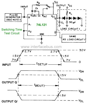
The pinout diagram for the 74L121 and 74L122 integrated circuits (ICs) is applicable to any style of 74xx121 or 74xx122 dual in-line package (DIP) chip, although the timing graphs are only relevant for the indicated TTL families. The 74121...
The GPS interface can be fed in 2 ways: with a stabilized 5V supply or with a 10 to 25V unregulated DC supply. In both cases, the power is fed into the RJ45 connector on point 8. Pin 7...
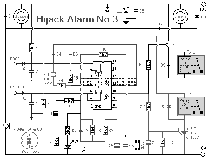
The Vehicle Anti-Hijack Alarm No3 is designed specifically for scenarios where a hijacker forcibly removes the driver from the vehicle. If any door is opened while the ignition is on, the circuit will activate. The Vehicle Anti-Hijack Alarm No3...
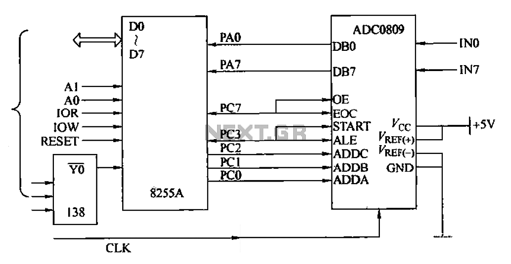
The ADC0809 is an 8-channel analog switch integrated with an 8-bit successive approximation analog-to-digital (A/D) converter. It supports the selection of eight input channels through address latch and encoder channel selection signals ADDA, ADDB, and ADDC. The address latch...
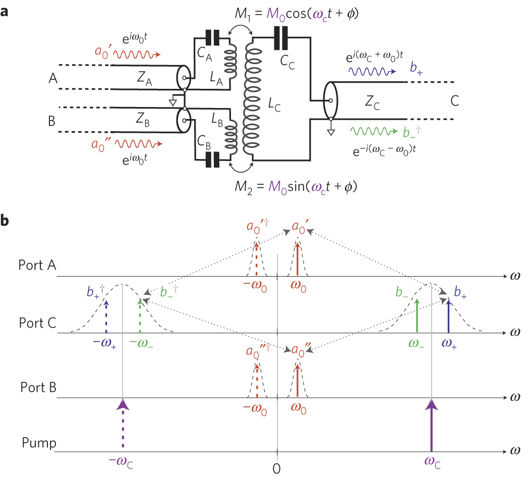
The circuit schematic of the UDC consists solely of dispersive components. Two low-frequency series LC resonators, with equal inductances (LA=LB) and capacitances (CA=CB), are connected to two input semi-infinite transmission lines, designated as A and B. These resonators are...
Warning: include(partials/cookie-banner.php): Failed to open stream: Permission denied in /var/www/html/nextgr/view-circuit.php on line 713
Warning: include(): Failed opening 'partials/cookie-banner.php' for inclusion (include_path='.:/usr/share/php') in /var/www/html/nextgr/view-circuit.php on line 713