
Auxiliary Lighting Circuit
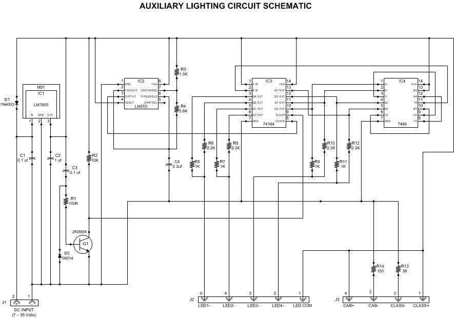
The lighting circuit employs a combination of discrete components to achieve the desired firebox glow effect and constant illumination. The primary elements include a power input connector (J1), a filtering capacitor (C1), and various resistors and transistors that control the flickering effect. The flickering effect simulates the dynamic nature of a real fire, achieved through a carefully designed timing circuit that modulates the voltage supplied to the LEDs or incandescent bulbs.
The circuit's design allows for flexibility in component selection, enabling users to adjust brightness and flickering speed according to personal preference. The schematic provides a clear layout for the arrangement of components, ensuring that builders can replicate the circuit accurately. The layout diagram further aids in the physical assembly of the circuit on a printed circuit board (PCB), showing the optimal positioning of components for effective heat dissipation and minimal interference.
In terms of installation, the circuit can be integrated seamlessly into a locomotive model. The constant voltage output can be routed to various lighting elements, enhancing the overall realism of the model. For locomotives equipped with DCC, the circuit's independence from the main power functions allows for consistent lighting regardless of the operational state of the locomotive. This feature is particularly advantageous for modelers seeking to create a lifelike operating environment.
Additionally, the circuit's compatibility with various power sources, including rechargeable battery packs and track power, ensures versatility in application. The ability to operate off a small battery further enhances the appeal for modelers who prioritize portability and ease of use. Overall, this circuit design provides an effective solution for achieving a realistic firebox glow and reliable interior lighting in model locomotives.This article describes a lighting circuit that generates a glowing firebox effect and provides constant illumination forclassification lamps and an interior cab light. It contains all information needed to build the circuit including a detailed schematic, circuit board layout diagram, and component parts list.
Recommended sources for components are provided. Instructions for typical installations are included. I like the effect of glowing fireboxes in my large-scale locomotives. Some locomotives come with a firebox glow circuit already installed; most usually do not. There are several commercially available fire flicker or electronic candle flame circuits that can be used to drive incandescent bulbs or LEDs in the firebox, but none of these look realistic to me. I wanted the effect to look like the shimmering, red-orange glow of a roaring fire in a coal-fired locomotive.
I decided to make my own. I figured while I was at it, I might as well add the capability to provide constant voltage forclassification lamps and locomotive cab interior lighting. I intentionally left out any capability to power the headlight since my locomotive headlights and reverse lights are powered directly from DCC controllers in my locomotives.
If you need to power a headlight, you can simply tap into the constant voltage provided by the circuit. This article will describe the circuit in sufficient detail to allow you to build identical copies or to modify it to meet your needs.
The circuit uses inexpensive discrete components that are available from a wide variety of sources. Potential suppliers are included with the components parts list. I bought enough parts to build five identical circuits and the total cost was under forty dollars less than eight dollars per locomotive. No special electronics skills are needed other than the ability to use a soldering iron. I operate all of my locomotives with onboard battery power. I use 14. 8 voltLi-ion batteries, QSI Sound/Power DCC controllers, and G-Wire radio receivers. This gives me a readily available source of constant DC power for the circuit from the onboard battery.
The circuit operates whenever the battery switch is in the ON position, regardless whether the locomotive is moving or not. It is totally independent of all throttle and sound functions from the QSI controller. If you run on analog power (straight DC track power), you can add a rectifier between your track pickups and the circuit to provide constant polarity DC power.
The downside of usingtrack power is that the circuit will not begin operating until the track voltage reaches 7 volts. If you run digital power (DCC track power), then you will always have the needed voltage available from the track pickups.
However, you would still needa bridge rectifier to maintain constant polarity. To eliminate the hassle of adding a bridge rectifier or dealing with other track power issues, an onboard battery is the best solution, even if you are operating from track power. The circuit can be powered from any small rechargeable battery pack between 7 and 35 volts. As a test, I ran the circuit continuously for over a week from a small 14. 8 volt, 2200mAh Li-ion battery pack on a single charge. The pack was the size of four AA penlight batteries. You could even run the circuit with a disposable 9-volt battery but the run time would drop to approximately 15 hours between battery changes.
Note: This section of the article explains how the circuit operates. You can skip on to the Circuit Description section unless you are curious or you want to make modifications. Refer to the schematic diagram in Figure 1 as you read this section. Input DC power is applied to connector J1. The input power can come from either an onboard battery, or from a bridge rectifier connected to the track inputs.
Connector J1 is keyed to prevent accidental polarity reversal. Capacitor C1 filters any transients on the in 🔗 External reference
Related Circuits
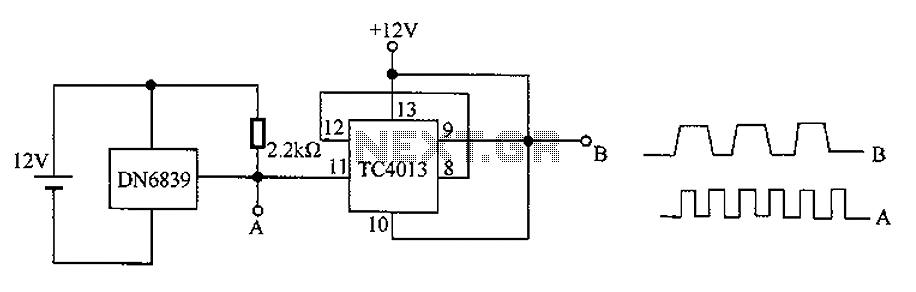
The circuit utilizes the integrated Hall element DN6839 for frequency division. It detects a magnetic field through the pulsating DN6839, generating a pulse waveform. The circuit is designed for applications involving very high-frequency pulsating magnetic fields. It employs the...
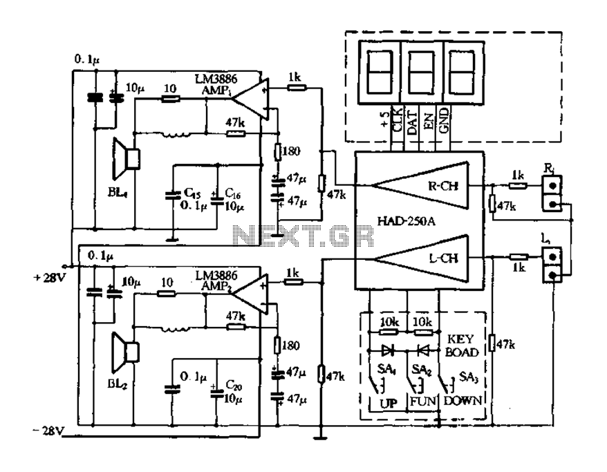
Figure 4-20 illustrates the HAD250A-3 active speakers and amplifier circuit, which features the LM3886 integrated amplifier. This circuit operates with a 25V power supply and delivers an output power of up to 50W per channel, making it suitable for...
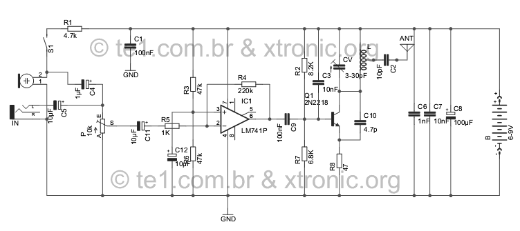
Evolution FM transmitter utilizing a 2N2218 transistor with an audio amplification stage using an LM741 operational amplifier. The design accommodates audio input from various sources such as MP3 players, MP4 devices, mobile phones, computers, and other audio sources, surpassing...
This circuit utilizes a sawtooth oscillator along with an output amplifier that drives a transistor. The components C1, C2, and L1 are essential for the oscillator's operation, forming a tank circuit that must be tuned to the resonant frequency....
The circuit comprises an N-MOSFET voltage follower (T1, common drain) and a current source (T2, NPN Darlington). The current source is set to 2.2 Amps. With a supply voltage of 40V, the circuit can deliver approximately 17W into an...
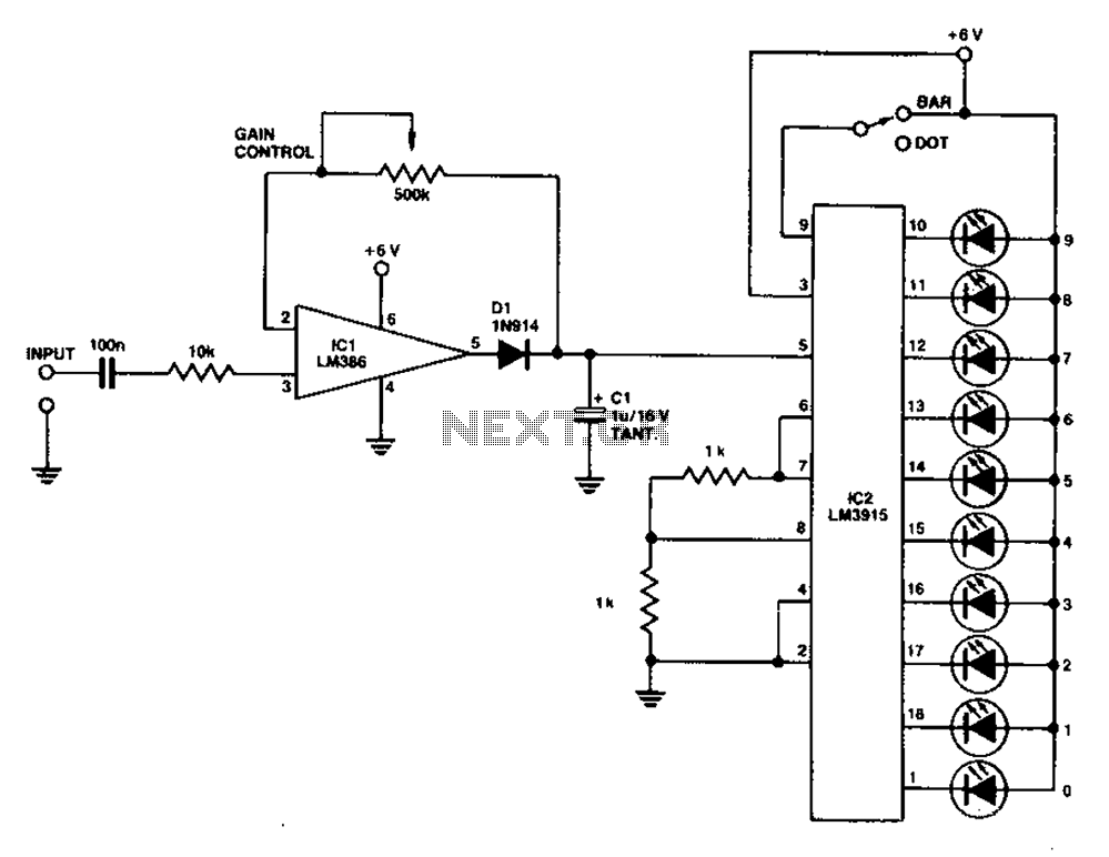
A simple level power meter designed to provide a high-fidelity sound system with a bar or dot matrix display. The green LED display indicates levels from 0 to 7; level 8 is shown in yellow, and level 9 is...