
Power Supply Circuit
The circuit operates as a high-fidelity audio amplifier, leveraging the characteristics of the N-MOSFET and NPN Darlington configurations to achieve low output resistance and high power efficiency. The N-MOSFET voltage follower configuration allows for high input impedance and low output impedance, making it suitable for driving loads such as loudspeakers. The Darlington pair serves as a robust current source, maintaining a steady output current even under varying load conditions.
The design emphasizes thermal management, suggesting that if the heatsink is not sufficient, adjustments to the supply voltage or quiescent current may be necessary to prevent overheating. The choice of transistors also plays a crucial role in ensuring reliability and performance under specified operating conditions. The circuit’s bandwidth and rise time indicate its capability to handle a wide range of audio frequencies without significant distortion, making it ideal for high-quality audio applications.
The inclusion of a potentiometer for volume control adds versatility to the circuit, allowing users to adjust the output level according to their preferences. Overall, the design is aimed at providing a powerful, efficient, and reliable audio amplification solution suitable for various audio applications.The circuit consists of N-MOSFET voltage follower T1 (common Drain) and current source T2 (NPN Darlington). Current source is set to 2. 2 Amps. With 40V of supply voltage the circuit is able to deliver about 17W into 8 Ohm loudspeaker. But takes 88W from power supply anytime. Bandwidth (-3dB) is from 4Hz to 250kHz. Rise time is 1. 5 us. Output resis tance 0. 16 Ohm. The circuit is very tolerant to different kinds of load. Input resistance is 10 kOhm (R0), but can be increased up to 100 kOhm (R4) when omitting R0. Input capacitance remains high, about 1500 pF. For this reason, the preamp should not have higher output impedance than 1 kOhm to maintain high frequency limit about 100 kHz. An input potentiometer can be used instead of R0. If the value of the potentiometer is 5 kOhm then the high frequency limit will be about 70 kHz. The power follower can be connected directly to the output of CD player and for reduction of volume the potentiometer 5 kOhm can be used.
Rod Elliott`s DoZ preamp is used (see or ). An article describing the use of this MOSFET power follower with Rod`s preamp can be seen at as "Project 83". The schematic of the DoZ preamp ( ©Rod Elliot, ESP, see his pages, and you can also order PCB`s for the DoZ from him.
) modified for this purpose can be seen in Fig. 2. To fulfill the specs of Q1-Q3 transistors, a supply voltage +Vs should be 30V. An experiment shows that they will survive supply voltage of 40V, so it is up to you to make a decision. It might be better to use BC547/BC557 as they are rated at 45V. When interconnecting the DoZ and the Follower, it is necessary to omit the R0 resistor of the follower.
This slightly modified circuit can be seen in Fig. 3. The complete amplifier is shown in Fig. 4. As shown, the gain is 3. 2, so it will require nearly 4V RMS input for full power. To increase the gain, you can change the R4 of the DoZ down to 1k to obtain a gain up to 23 (27 dB). Then increase the value of C3 to 47uF. The gain can be calculated as G = 1 + (R5/R4). Distortion figure shows the harmonic distortion curve from 15 milliwats to 6 Watts at 1. 8kHz and 8 Ohms for 7W version of the Follower with DoZ preamp. The distortion is mostly second harmonic. P. S. You may reduce the supply voltage or quiescent current if your heatsink is not good enough. 30V of supply voltage will give you about 10W/8 Ohm. R7 will be then used to trim a current through zener diode 3V to maintain appropriate quiescent current through R6. This current (the current of constant current source T2) can be easily measured - a voltage drop in Volts accross R6 resistor has the same value as the current through T2 in Amps, because of the R6 value (1 Ohm).
In case you reduce quiescent current to 1. 4 A (at 40V of supply voltage) you will get about 8W/8 Ohm. Take care about zener voltage of the ZD3V. I use the BZX83 type, 0. 5W, 3V zener diode. This diode gives proper zener voltage between 3. 0V to 3. 3V. In case you use bigger diode (1. 3W, 2W etc. ), most likely you will get different zener voltage, resulting in wrong quiescent current of the follower. Always check the zener voltage in this real circuit! The quiescent current equals (zener voltage - Vbe of T2)/R6. And check voltage across R6, as quiescent current is 🔗 External reference
Related Circuits
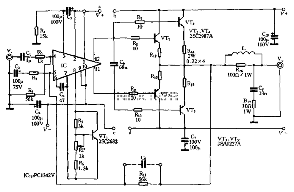
The pLPC1342V and NE are two companies involved in a tube amplifier circuit utilizing 2SA1227A and 2SC2987A transistors, achieving a maximum output power of up to 120W with a cutoff frequency of up to 500 MHz. The circuit, illustrated...
Colour sensor is an interesting project for hobbyists. The circuit can sense eight colours, i.e. blue, green and red (primary colours); magenta, yellow and cyan (secondary colours); and black and white. The circuit is based on the fundamentals of...
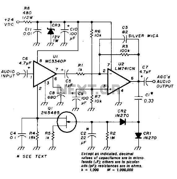
An audio signal applied to the input VI is passed through the operational amplifier 741, designated as U2. After amplification, the output signal V2 is sampled and sent to a negative voltage doubler/rectifier circuit composed of diodes CR1 and...
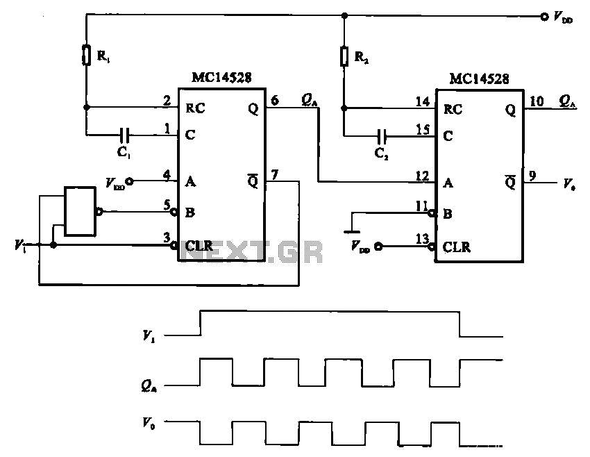
The pulse generating circuit monitors signals using monostable flip-flops. It generates a single-shot output signal based on the input pulse signal. A key signal from the monostable flip-flops is represented in a formula, with the input (V1) and output...
This picture and schematic were intended for posting on my Watson's blog, but it did not get published. The circuit schematic in question likely includes various electronic components arranged to perform a specific function. Typically, such schematics are used to...
This article is intended for individuals interested in constructing their own car amplifier. The fundamental calculations will be discussed below. Understanding these concepts will enable the construction of a car amplifier independently. The challenge in designing a car power...