
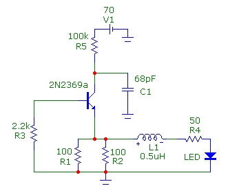
Saw Transmitter Circuit

The circuit comprises several key elements that work together to produce a stable output frequency. The sawtooth oscillator generates a waveform that is characterized by a linear rise and a sudden drop, which is ideal for applications requiring precise timing signals. The oscillator's frequency is primarily determined by the values of C1, C2, and L1, where the inductance of L1 and the capacitance of C1 and C2 create a resonant tank circuit.
In this configuration, C1 is typically chosen to have a smaller capacitance compared to C2, allowing for fine-tuning of the oscillator frequency. The combination of these capacitors with the inductor L1 ensures that the circuit resonates at the desired frequency, which is crucial for maintaining the stability and efficiency of the oscillator.
The output amplifier is responsible for boosting the signal generated by the oscillator, driving a transistor that further amplifies the output to a level suitable for transmission. This transistor acts as a switch, allowing the oscillator's output to control larger currents necessary for driving an antenna.
The output network, consisting of an additional capacitor and inductor, serves a dual purpose. It not only matches the impedance of the antenna to the output of the amplifier but also filters harmonics that may be present in the output signal, ensuring that the transmitted signal is clean and within the desired frequency band. Proper impedance matching is critical in maximizing power transfer and minimizing signal reflections.
Overall, this circuit is designed for applications in radio frequency transmission, where precise control over frequency and signal integrity is paramount. The careful selection and arrangement of components ensure that the circuit operates efficiently and reliably, making it suitable for various communication systems.This circuit uses a saw based oscillator with an output amplifier which drives a transistor. C1 and C2 and L1 are critical oscillator components. They form a tank circuit which should be tuned to the resonator frequency. Typically C1
Related Circuits
This article presents basic circuits for pulsing infrared LEDs and low-power visible semiconductor lasers utilizing inexpensive and readily available components. Numerous interesting and practical applications are referenced, alongside several online resources. The focus of the article is on the...
This circuit is a simple 12V DC to 220V AC inverter that produces an AC output at line frequency, specifically 220V AC, or other voltages by selecting transformer T1. The 555 integrated circuit (IC) is configured as a low-frequency...
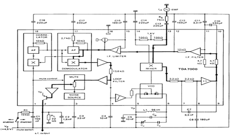
The TDA7000 is an integrated circuit (IC) designed for FM portable radios, featuring a Frequency-Locked Loop (FLL) system with an intermediate frequency of 70 kHz. It incorporates several functions, including an RF input stage, mixer, local oscillator, IF demodulator,...
The RF oscillator utilizes inverter N2 and a 10.7 MHz ceramic filter to drive the parallel combination of inverters N4 to N6 through inverter N3. Since these inverters are connected in parallel, the output impedance is low, allowing direct...
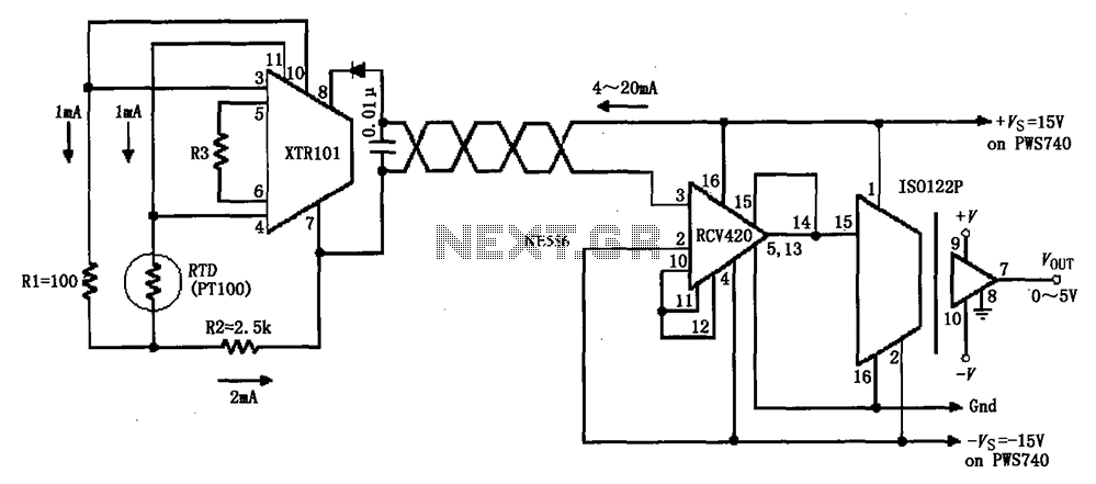
The circuit comprises an isolated RTD loop current configuration utilizing the XTR101 for transmitting loop current and the RCV420 for receiving it. The instrumentation amplifier detects changes in temperature via a resistance temperature detector (RTD), converting these changes into...
The circuit diagram is designed for precise control of DC motors. It converts DC voltage into a series of pulses, where the duration of each pulse... The circuit utilizes a pulse-width modulation (PWM) technique to regulate the speed and torque...