
AV Switch circuit

The design described is for a compact, low-cost signal router capable of routing any of eight audio inputs and eight video inputs to two pairs of outputs. It includes a DTMF tone generator and an automatic antenna selector circuit. All functions are controlled via a pair of keypads: the function keypad determines the mode while the numeric keypad allows for digit or channel selection. Antenna selection can be performed by pressing the "AS" function key or grounding a pin on the PCB. This pin can be connected to a transmitter to automatically select the preferred antenna each time a transmission starts. The desired antenna number is programmed by fitting links or a small switch to the smallest of the PCBs. The power-up condition sets the keypad in DTMF mode with channel 1 video and sound routed to both A and B channel outputs. The "both" function selects audio and video channels simultaneously; for instance, pressing "Chan B both" followed by the 5 key will route audio input 5 to channel B audio output and video input 5 to channel B video output. The "video" keys modify the selected video output only, retaining the current audio selection. For example, pressing "Chan B video" followed by 2 would select video input 2 while continuing to pass audio from input 5.
All five boards can be fabricated from a single standard Eurocard (160x100mm) PCB. The two 95-003D boards are mounted upright from the main board, minimizing video and audio track lengths to reduce crosstalk. The function key PCB is designed to match the height of the numeric keypad for straightforward front panel mounting. The small board that accommodates the antenna enable and selection links can be mounted on the rear panel since it does not require frequent adjustments. Assembly should start with fitting all resistors, followed by capacitors and diodes. Wire clippings can be repurposed for mounting the upright PCBs later. It is crucial to ensure that all upright diodes are installed with the cathode (banded) end facing upwards. Following this, the links, remaining components, and finally the ICs should be installed. The PIC16C54 must be programmed prior to soldering it in place, as an unprogrammed device will be non-functional. The binary object file necessary for programming will be available on the BATC website. For those unable to program the devices themselves, assistance can be sought. When positioning the upright boards, their bottom edges should rest flat against the main PCB with components oriented towards the nearest edge.Before applying power, check for shorts on the board. This design runs from a FIVE volt supply, connecting it directly to a 12 volt supply will kill it for certain. The current drawn is very small, in the region of 70mA so connect a small 5V regulator in line with the supply if you intend to use a 12V power source.
For the prototypes I used a stan dard 7805 regulator on a 2cm square copper sheet and even after running for two days it was barely warm to touch. When you are happy that the current consumption is OK, measure the voltage between ground and each of the outputs, it should be less than 0.
5V. If all is well you can connect a monitor to the video and audio outputs then put the unit in "self-test" mode by pressing the "Chan A both" and "DTMF" function keys simultaneously. You should hear alternating high and low pitched beeps at about 1 second intervals. Next, connect some audio and video sources to the inputs, in self-test mode the inputs are selected in sequence so you should see and hear the sources being selected one after another.
Channel A and B sequences are staggered so you can confirm their independent operation. To exit "self-test" mode you can either switch the power off and on again or press and hold the "Chan B both" and "Antenna select" keys together until a rapid beeping is heard. You can release the keys as soon as the beeps start and after a few seconds the unit will initialise itself to its newly powered up state.
The design described here is for a compact, low-cost signal router that can feed any of eight audio inputs and eight video inputs to two pairs of outputs. It also includes a DTMF tone generator and an automatic antenna selector circuit. All the functions are controlled from a pair of keypads, the function keypad decides on which mode is to be used while the numeric keypad allows digit or channel selection.
Antenna selection is achieved by pressing the "AS" function key or by grounding a pin on the PCB. By connecting this pin to your transmitter it is possible to automatically select your preferred antenna every time you start a transmission. The desired antenna number is programmed by fitting links or a small switch to the smallest of the PCBs.
The power-up condition is for the keypad to be in DTMF mode with channel 1 video and sound being fed to both A and B channel outputs. The "both" function selects the audio and video channel together. For example pressing "Chan B both" followed by the 5 key will send audio input 5 to channel B audio output and video input 5 to channel B video output.
The "video" keys only change the selected video output, leaving the sound selection as it was. Using the example above, pressing "Chan B video" then 2 would select video input 2 while still passing the sound from audio input 5. All five boards can be cut from one standard Eurocard (160x100mm) PCB. The two 95-003D boards are mounted upright from the main board, this method minimises the video and audio track lengths so reducing the cross-talk between them.
The function key PCB is the same height as the numeric keypad to make front panel mounting easy. The small board houses the antenna enable and selection links, as these will not require frequent adjustment, it can be mounted on the rear panel. Fit all the resistors first, then the capacitors and diodes. Keep all the wire clippings, they can be used to mount the upright PCBs later on. Note that all the upright diodes are mounted with the cathode (banded) end topmost. Next, fit the links, remaining components and finally the ICs. The PIC16C54 must be programmed before soldering it in place, an unprogrammed device will not work. The binary object file will be available on BATC web site. Contact me if you need devices programming and can`t do it yourself. When mounting the upright boards their bottom edge should sit flat on the main PCB with the components facing its nearest edge.
Fold the wire lin 🔗 External reference
Related Circuits
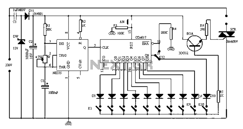
Figure 1-1 illustrates a general-purpose timer capable of timing intervals ranging from 5 minutes to 18 hours. The timing cycle can be adjusted to span from 5 minutes to 20 hours, with a maximum control time of 18 hours....
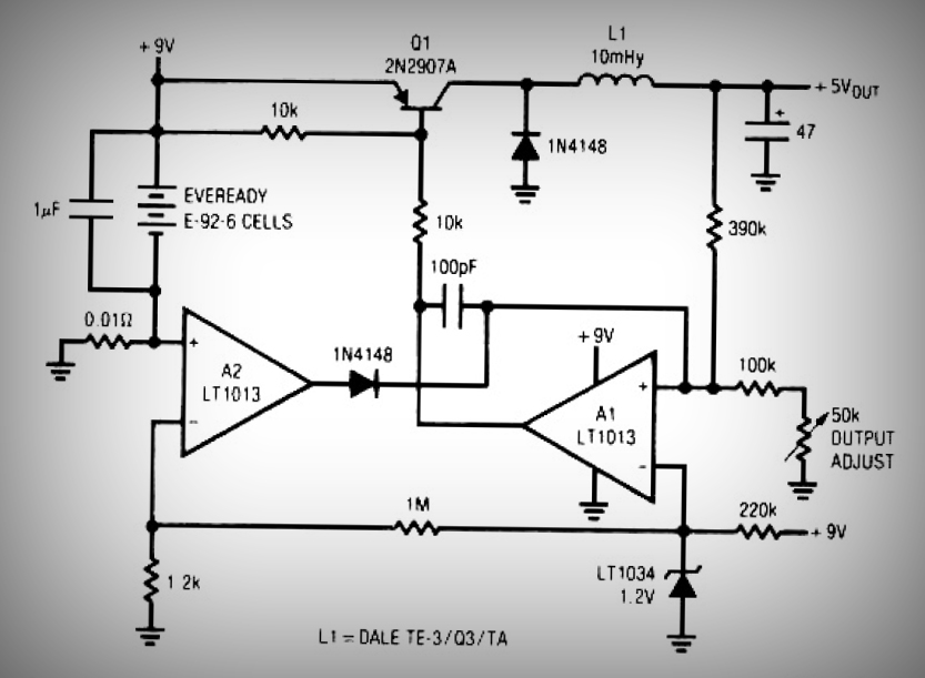
This circuit is a simple battery-powered switching regulator that provides a 5V output from a 9V source with 80% efficiency and a 50 mA output capability. When Q1 is on, its collector voltage increases, causing current to flow through...
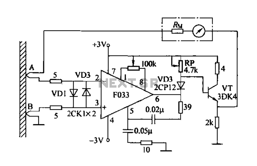
Detecting electrical equipment sometimes requires disconnecting the circuit in series for more accurate measurements of electrical current using an ammeter. However, restoring the circuit to its original state is necessary, as it can affect the normal operation of electrical...
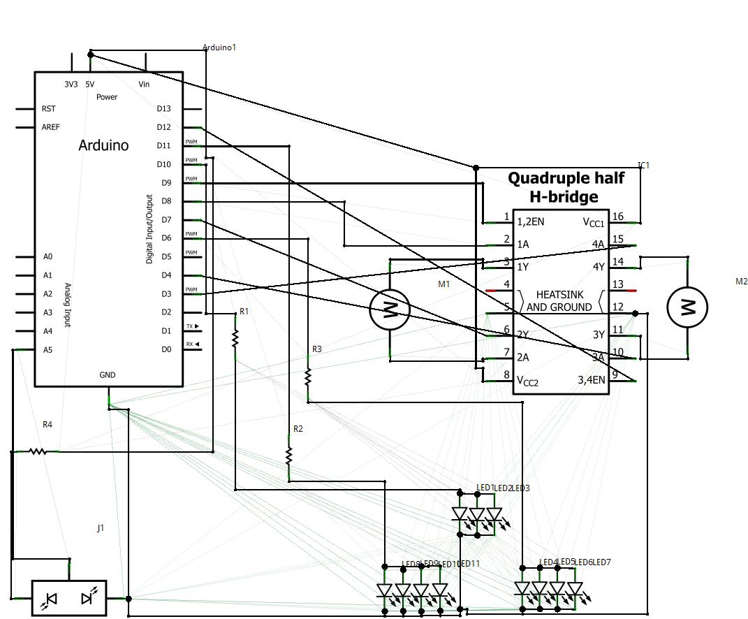
1. Abstract Wet-garden is an interactive flower garden and an ambient indoor sculpture. When people walk around it, it changes motion and LED blinking speed. Wet-design is designed for everyone who wants a tangible interaction object and an interesting...
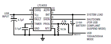
The schematic presented illustrates a minimal component solution for a USB battery charger utilizing the LTC4053 integrated circuit (IC) to create a fully compliant USB charger. This IC functions as a standalone linear charger designed for lithium-ion (Li-ion) batteries,...

The figure illustrates the circuit diagram of a multi-tone alarm, which fundamentally operates as an amplifier circuit. The core component of this circuit is the dual. The multi-tone alarm circuit is designed to produce various sound tones, enhancing its alerting...