
Line current measurement circuit
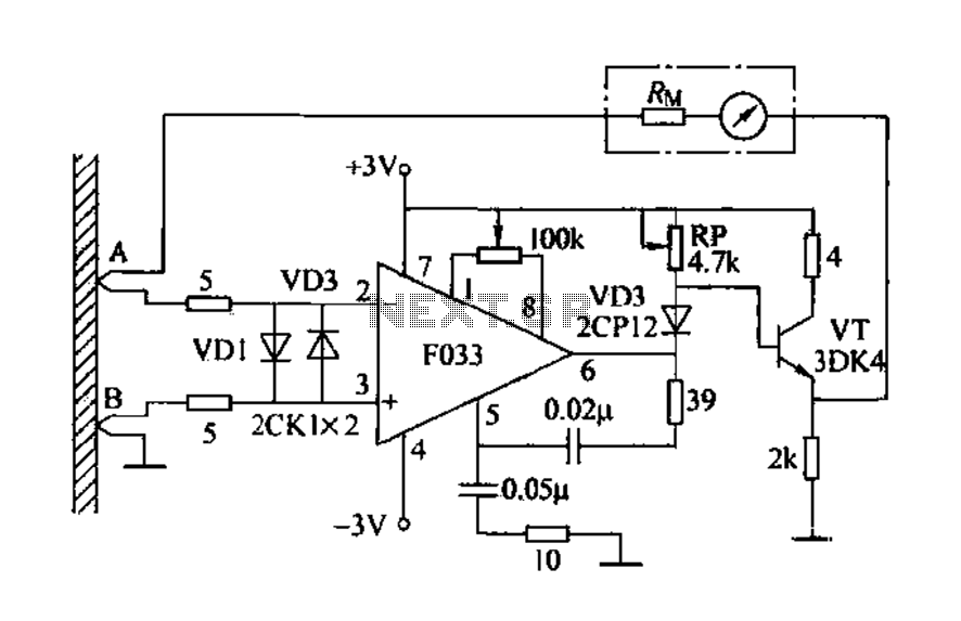
The circuit includes a 50VA resistance ammeter (RM) set at 2 kΩ, with a full-scale voltage drop (UD) of 50 µA, which is 100 mV, well within the op-amp's linear dynamic range. The most sensitive current profile is at 1 mA, with the feedback branch equivalent resistance (RM) calculated at 100 Ω for 1 mA. The op-amps open-loop gain (G) is -120 dB (10^6 times), leading to a virtual ground equivalent resistance (Rmf) of RM/G, which results in 100 Ω for 1 mA. The copper equivalent resistance remains low at this current source, with the internal resistance measured across a slip resistance wire to a 1 mm wide printed circuit board copper foil. If the distance between two probes (length segment AB) on the copper foil is 1 cm, the equivalent electrical resistance (Rt) would be 2 Ω, introducing a wind error of 5%. If the probe length is increased to 5 cm, the error decreases to 1%.
It is evident that the open-loop gain (Gv) of the op-amp is a critical factor influencing measurement error; thus, selecting a high-gain operational amplifier can help reduce this error. Additionally, input offset and internal noise can introduce further inaccuracies, necessitating the use of low-drift op-amps with high input impedance. The circuit employs a low-drift op-amp (F033), yielding a measurement error of approximately 2%, which meets the requirements. Utilizing auto-zero operational amplifiers (such as the 5G7650) would further enhance performance. The circuit also incorporates a transistor (3DK4) to increase power capacity, while diodes (VD1, VD2) provide protection for the two input tubes, and diode (VD3) serves as a level shifter for the transistor (VT) and VD3 operating point.Detecting electrical equipment, sometimes in order to more accurately measure the electrical current, the need to disconnect the circuit in series into the ammeter measurements , although the need to restore the status quo ante after the circuit, which not only affect the normal operation of electrical equipment line, and may cause new hidden faults. If a line current measuring instrument, it does not damage the circuit board. Can be achieved online current measurements. 6-52 the line current measuring circuit shown in Fig. It is the advantage of the operational amplifier with negative feedback, its virtual ground point-to-ground input into the resistance is minimal.
When it is a printed circuit board with copper foil in parallel, forced flow through the foil to change the current flowing through the op amp feedback branch (header branch road), in order to achieve without affecting the normal operation of electrical equipment situation under conditions, the measured current of a branch. FIG 50VA resistance ammeter RM 2kfl, meter full scale voltage drop UD a 50yA 2kfZ lOOmV, far beyond this voltage op amps linear dynamic range.
If the measured current profile as a most sensitive ImA. The feedback branch of the equivalent resistance RM a lOOrrN/lrriA a ioon. Let op amps open-loop gain G, -120dB [lOf/times], the location of the virtual ground op amp equivalent resistance Rmf RM/G, lOOfl/L06 0; ImfZ. Copper equivalent resistance is very small at this current source, the internal resistance is measured period of slip resistance wire to Imm wide printed circuit board copper foil for the side, measured obtaining the resistivity of 2mfl/cm.
If the distance between the two probes (AB segment length) on the copper foil is lcni, a current source equivalent electrical resistance Rt a 2rrd: l !. Therefore, the wind error introduced by 5%. If. NB length of 5cm, the error introduced by Rs 1%. Obviously op amps open loop gain Gv is one of the key factors affecting the measurement error, the choice of high-gain op knock, homes help reduce measurement error.
Furthermore, open transport input offset and internal noise will cause error, so, the choice of high gain knock, while also taking into account the low-drift op amp, low noise and high input impedance into. The circuit uses low-drift op amp F033 test result is a file in the most sensitive hands swinging a small cell (ie, error of 2%), basically meet the requirements.
If you use auto-zero operational amplifiers (such as 5G7650, etc.), it would be better. Circuit transistor 3DK4 push to increase power capacity. VD1, VD2 for the protection of two input Xi tube. VD3 for the level shifter tube with spectral section to the transistor VT and VD3 operating point.
Related Circuits

This circuit was first introduced by Signetics Corporation as the SE555/NE555 around 1971. Pin connections and functions are as follows: Pin 1 (Ground) is the most negative supply potential of the device, typically connected to circuit common when powered...

The modification of the differential circuit is illustrated. In Figure A1, an integrator is depicted, and the output is presented. The circuit modification involves integrating the differential circuit with an integrator component, which plays a crucial role in signal processing...
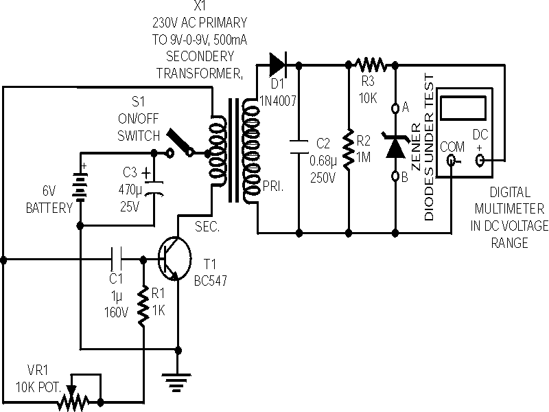
Here is a handy zener diode tester which tests zener diodes with breakdown voltages extending up to 120 volts. The main advantage of this circuit is that it works with a voltage as low as 6V DC and consumes...
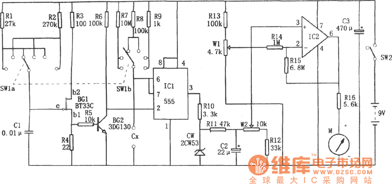
A DC capacitor tester circuit diagram utilizing a 555 timer is presented. The tester includes a pulse generator, a one-shot circuit, a DC amplifier, and a meter indication circuit. It is capable of measuring capacitors ranging from nanofarads (nF)...
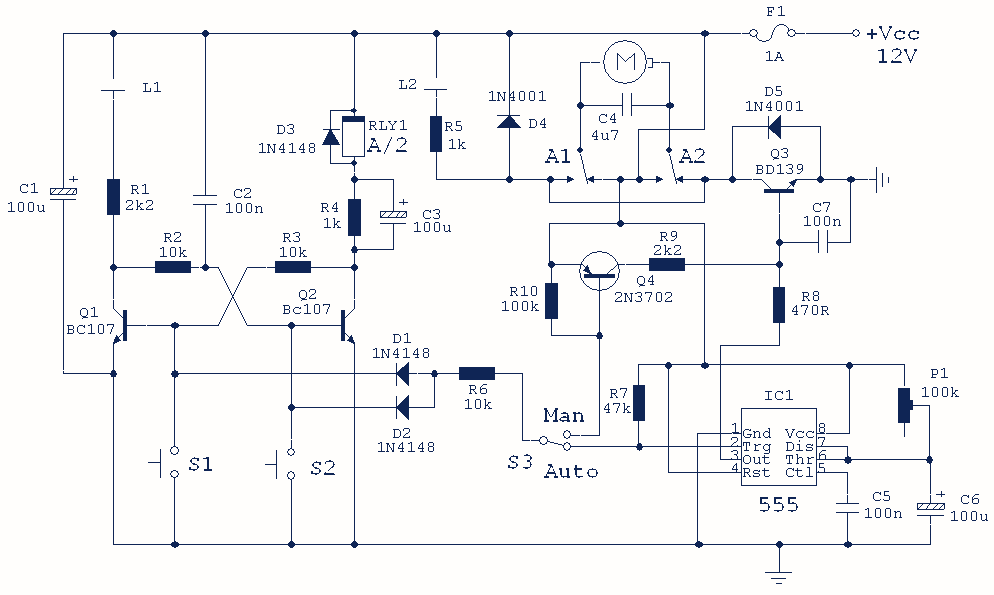
This hybrid circuit uses a mixture of transistors, an IC and a relay and is used to automatically open or close a pair of curtains. Using switch S3 also allows manual control, allowing for curtains to be left only...
Any standard oscillator, such as a Colpitts or Hartley configuration, can be utilized to generate the local oscillator (LO) frequency required by the NE602. The NE602 is a versatile integrated circuit commonly used in radio frequency applications, particularly in mixer...