
USB Battery Charger Components and Circuit using LTC4053
The LTC4053 is engineered to provide a straightforward charging solution for Li-ion batteries, ensuring compliance with USB charging standards. It incorporates features such as automatic detection of the battery voltage, constant current (CC) and constant voltage (CV) charging modes, and thermal regulation to prevent overheating during the charging process.
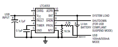
In the schematic, the LTC4053 is connected to a USB power source, typically providing 5V. The IC manages the charging cycle by controlling the current flowing into the battery. Key components in the circuit include input capacitors for power stabilization, a resistor network for setting the charge current, and output capacitors to smooth the voltage supplied to the battery.
The charger circuit also includes a feedback loop that monitors the battery voltage. When the battery reaches its full charge, the LTC4053 automatically switches to a trickle charge mode to maintain the battery's charge without overcharging. This feature is crucial for prolonging battery life and ensuring safety during operation.
Overall, the LTC4053-based USB charger circuit is an efficient and reliable solution for charging Li-ion batteries, suitable for various portable electronic devices. Its simplicity and adherence to USB standards make it a preferred choice for engineers looking to integrate battery charging capabilities into their designs.The schematic herein shows a minimum component solution to the USB battery charger using LTC4053 IC to achieve a fully compliant USB charger. This IC is a standalone linear charger for lithium ion (li-ion) batteries that can be powered directly from a USB port, according to the datasheet
🔗 External reference
Related Circuits

This circuit utilizes a Power Battery Terminal (PBT) to facilitate simple relay output and auxiliary power connections. An LED on each channel serves to indicate the status of the relay. Berg pins are provided for connecting power and trigger...
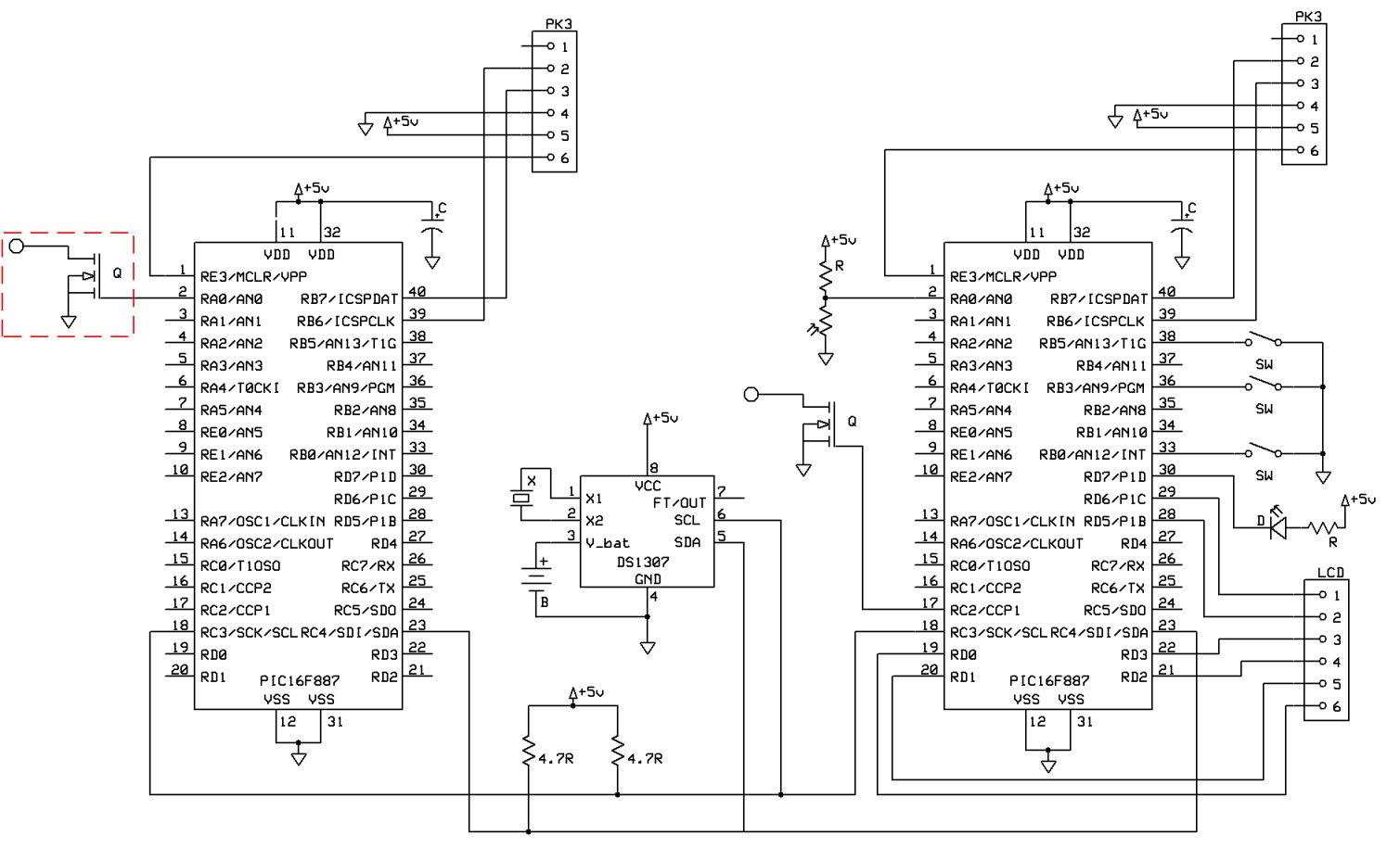
8051SBC USB and GLCD Expansion Board, electronic circuit schematic wiring diagram for the 8051SBC USB and GLCD Expansion Board. The 8051SBC USB and GLCD Expansion Board is designed to enhance the functionality of the 8051 microcontroller system by providing additional...
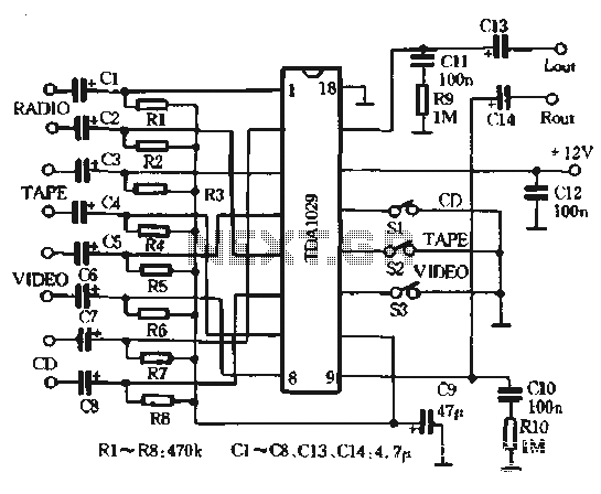
The AV combination as depicted in the diagram involves the first stage using the Philips TDA1029, which functions as a four-input switching signal processor. The second stage employs the NE5532 as a preamplifier, while the B of the NEC,...
A new post has been created regarding the Sunrise Word Clock project. The initial attempt to implement the circuit on a breadboard was unsuccessful, likely due to inadequate connections and suboptimal layout choices. The project has been rebuilt with...
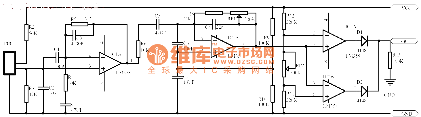
Passive human body infrared sensor circuits are generally similar in design, although some may have fewer stages. The circuit illustrated is sourced from the NICERA manufacturer and is considered a classic example. The front-end stage consists of a low-frequency...
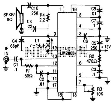
An LM2808 performs IF amplification of the 4.5-MHz sound subcarrier, limiting, detection, and audio amplification. If the center frequency must be changed, then change L1/C4. Audio output is 0.5 W. R3 is the volume control. The LM2808 is an integrated...