
baby Tesla coil

The inverter circuit operates by converting DC voltage into high-frequency AC voltage, which is then transformed to a higher voltage level. The use of a MOSFET like the IRF840 is crucial due to its capability to handle high switching speeds, essential for efficiently driving the transformer. The circuit typically consists of a DC power source, the MOSFET, a transformer, and the output components, including the resistor R2 which plays a vital role in tuning the frequency of the inverter.
The transformer used in this application should be capable of handling high voltages and must be designed to operate at the frequency generated by the MOSFET. The output from the transformer can be rectified and filtered if necessary, depending on the application requirements. The selection of the transformer is critical; it must be capable of stepping up the voltage safely and efficiently.
R2 functions as a feedback resistor that influences the oscillation frequency of the inverter circuit. By adjusting its value, the user can modify the operating frequency, which in turn affects the pitch of the sound produced by the plasma. The buzzing sound is a direct result of the rapid switching of the MOSFET and the resonant behavior of the circuit.
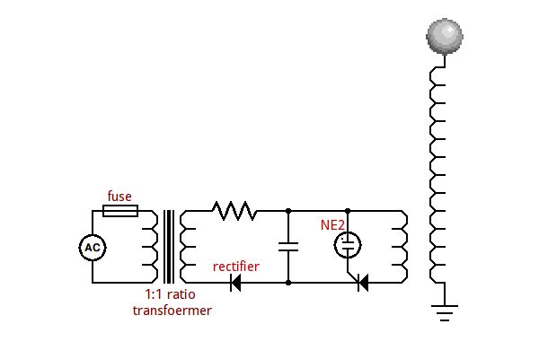
Safety precautions should be taken when working with high voltages, as the output can be lethal. Proper insulation, protective equipment, and adherence to safety standards are essential when constructing and testing this inverter circuit. Additionally, experimentation with different MOSFETs and transformer configurations can yield varying results, allowing for optimization of the plasma generation characteristics.Inverter circuit to power EL backlights and fluorescent tubes, so the output is about 127 VAC as he claimed. But I want 1kV or more to make at least 1mm purple plasma as Tesla coil usually produce! (30kV is required to make 1cm length plasma). Therefore i use MOSFET IRF 840 as a transistor for high switching rate (also any IRF-named MOSFET will do, such
as IRF741 and 630) and also transformer i use before from cracking open a battery charger to step up the voltage to more than 1kV. R2: 464kOhm or more, up to you ( you experiment it yourself). This resistor controls the frequency so different values produce different sound pitches of the plasma ( it produces buzzing sound depending on its operating frequency)
🔗 External reference
Related Circuits
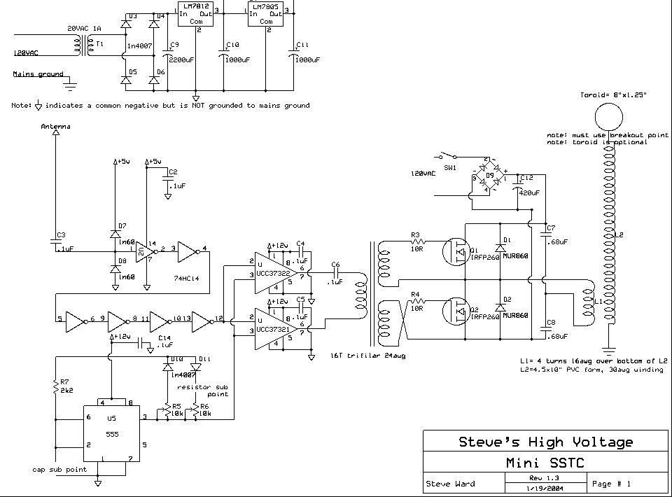
The design is a clone of Steve Ward's MiniSSTC circuit; the schematic is reprinted here with credits to Steve Ward. This circuit performs very well for a low power and simple SSTC. The design is based on Steve's final...
An SCR (Silicon Controlled Rectifier) functions similarly to a diode, allowing current to flow in one direction and can be turned on; it remains in this state until the power is interrupted. The query arises regarding its application in...
This circuit is designed to demonstrate high frequency and high voltage, capable of producing up to approximately 30 kV, depending on the transformer utilized. It is an economical and straightforward project, primarily using a standard TV flyback transformer. The...
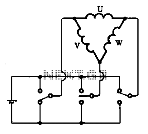
A stator coil connection illustrates the structure and connections of the stator coil. Figure (A) depicts a triangular connection, while Figure (B) illustrates a star connection, presented in two forms. The stator coil is a critical component in electric machines,...
The description pertains to a specific type of preamplifiers that are designed to amplify the low output of Moving coil heads, enabling their drive to an input PHONO [RIAA] of a preamplifier. Moving coil heads present certain challenges that require...
Every inexpensive energy-saving lamp contains a self-resonant voltage inverter designed for low-power operation, typically up to a few watts. It raises the question of why not scale up this concept and replace the resonance circuit used to generate the...