
Solid State Tesla Coil/High Voltage Generator Circuit
The transformer requires rewinding of its primary coil. Initially, the old primary must be removed carefully to avoid damaging the high voltage secondary. If the windings are encased in plastic, an alternative transformer should be sourced. The new primary should consist of five turns of 18 AWG wire, with a center tap loop, followed by an additional five turns. This configuration forms winding C-D. Additionally, two turns of 22 AWG wire should be wound, twisted into a loop, and followed by another two turns to create winding A-B.
Transistors Q1 and Q2 will generate significant heat and should be mounted on a large heatsink. After operating for a minute or two, the transistors should remain cool enough to touch without causing burns. Resistors R1 and R2 will also heat up during operation. If arcing occurs on the exposed leads of the transformer, a lower voltage setting for T1 should be selected. When using a power supply, the voltage can be adjusted accordingly.
The circuit can be visualized in two configurations: one without a voltage multiplier, which shows a visible arc, and one with a voltage multiplier, resulting in a brighter arc. Safety precautions are crucial when operating the high voltage generator. It is recommended to stand on a non-conductive surface, such as a pie plate on top of a plastic bucket, while the generator is in use, ensuring that someone else operates the power switch. It is essential to avoid touching any objects while charged and to remove any metallic accessories, such as watches.
To construct this high voltage generator, the following steps outline the necessary components and assembly process. The circuit primarily consists of a flyback transformer, which is critical for stepping up the voltage. The rewinding process is essential to ensure optimal performance and safety. Proper heat management for the transistors is vital to prevent damage and maintain functionality. The use of resistors in the circuit aids in current limiting, contributing to the overall stability of the operation.
In terms of safety, the circuit poses significant risks associated with high voltage. Proper precautions must be taken to avoid electric shock or injury. It is recommended that only individuals with adequate knowledge and experience in handling high voltage circuits attempt to build and operate this generator. The use of insulated tools and protective gear is advisable to mitigate risks during the assembly and testing phases.This is a fun and useful circuit for demonstrating high frequency high voltge. It can produce up to about 30KV, depending on the transformer used. It is cheap and easy to make, thanks to the standard TV flyback transformer used. It can power LASERS (although I have never tried), demonstrate St. Elmo`s fire, and even cause a fluorescent bulb to ligh t from as much as 2 feet away. 1. T2 is a high voltage flyback transformer salvaged from an old TV, or ordered from Fair Radio Sales (see Where To Get Parts). Look for the biggest, most intimidating transformer you can find. Old tube TV`s are a good place to look. The transformer should not have a rectifier built in. 2. You will need to rewind the transformer`s primary. First, remove the old primary, being careful not to damage the high voltage secondary. If the transformer is wound with all windings incased in plastic, use another transformer. Second, wind on 5 turns of 18 AWG wire, twist a loop (center tap), and then wind on 5 more turns. This becomes winding C-D. Now, wind on 2 turns of 22 AWG wire, twist a loop, and wind on 2 more turns. This becomes winding A-B. 3. Q1 and Q2 will run HOT if not used with a large heatsink. After the circuit has been running for a minute or two, you should still be able to put your finger on the transistors without being burnt.
Also, R1 and R2 will run hot. 4. If you experience arcing on the exposed transformer leads, select a lower voltage for T1. If you are powering the circuit with a power supply (see Power Supply ), just crank down the voltage. The first picture is the high voltage generator without the voltage multiplier. Notice how hot the arc looks. The second picture is the high voltage generator with a voltage multiplier installed. Notice how much brighter the arc is. The above pictures of myself were taken with me standing on an pie plate that was resting on the top of a plastic bucket.
The pie plate was connected to the high voltage generator and charged to about 40, 000V. If you do this, be sure to have someone else turn on and off the high voltage generator. Also, don`t touch anything when you are charged. Have everything you are going to hold/play with already sitting on the bucket and away from grounded objects. Remember to take off your watch. 🔗 External reference
Related Circuits
At the beginning of the design process, the designer must determine which circuit structure is appropriate for a specific purpose. During this phase, numerical and symbolic analysis are of limited utility. There are no numerical values available for conventional...

Phase noise is a critical performance parameter of frequency synthesizers for wireless applications. RF system designers of phase-modulated cellular systems, such as PHS, GSM, and IS-54, require low noise local oscillator (L.O.) or frequency synthesizer blocks. This document describes...
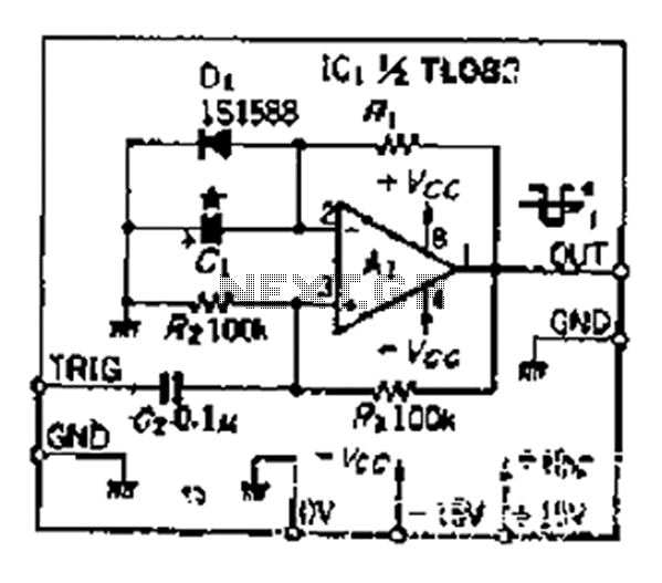
Although people believe that using a timer with an operational amplifier (op-amp) does not yield significant results, it can still be advantageous in certain scenarios. In environments with high noise levels, the application retains its benefits. When the phase...
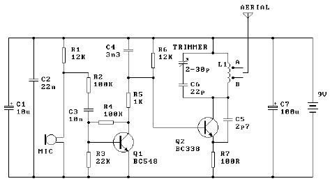
The tuned coil L1 has two output tap points for the antenna connection, labeled "A" and "B." Both outputs are low-level, allowing the user to select between a stable low range or a more unstable but higher range. Tap...
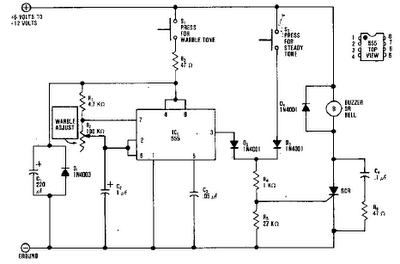
A basic square wave generator has been designed to operate a speedometer circuit board, which is responsible for controlling various functions. The square wave generator circuit typically consists of a few key components: a timer IC, such as the 555...
The purpose of this timer is to disconnect the compressor circuit and connect a resistive heating element located near the evaporator at regular time intervals. The defrost heater is controlled by a thermostat and is used to melt any...
Warning: include(partials/cookie-banner.php): Failed to open stream: Permission denied in /var/www/html/nextgr/view-circuit.php on line 713
Warning: include(): Failed opening 'partials/cookie-banner.php' for inclusion (include_path='.:/usr/share/php') in /var/www/html/nextgr/view-circuit.php on line 713