
Balance Indicator for Symmetric Power Supply

The balance indicator circuit employs the LM339N quad comparator to assess the symmetry of a dual power supply. This device contains four independent comparators, enabling the design of two pairs that can be used to compare the voltage levels of the positive and negative rails of the power supply.
The circuit is configured such that each comparator in the pair receives input from one of the power supply rails. The reference voltage for comparison can be set to ground or a predefined voltage level, depending on the desired sensitivity of the indicator. When the voltages on the two rails are equal, the outputs of the comparators will reflect this balance, providing a clear indication of symmetry.
The outputs from the comparators can be connected to LED indicators or a display module to visually represent the symmetry status. If the voltage levels deviate, the corresponding LED will illuminate, signaling an imbalance in the power supply. This visual feedback allows for quick diagnostics and ensures that the power supply operates within the required specifications for balanced performance.
In practical applications, this balance indicator can be integrated into power supply units used in audio equipment, instrumentation, and other electronic systems where voltage symmetry is crucial for optimal operation. The simplicity and effectiveness of using LM339N comparators make this circuit an efficient solution for monitoring power supply balance.Balance indicator for power supply show if a symmetric power supply is really symmetric or not. With two comparator pairs from a LM339N quad comparator we.. 🔗 External reference
Related Circuits

This design concept outlines a 12-V DC to 5-V DC (±5%) switched-mode power supply (SMPS). The supply utilizes a 12-V input derived from an array of four 3-V DC, 40-mA solar cells connected in series. The proposed switched-mode power supply...
The diagram illustrates the circuit of a versatile USB power socket that safely converts 12V battery voltage into a stable 5V output. This circuit enables the use of various USB-powered devices. The circuit design consists of several key components to...
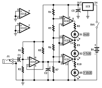
No setup is required: if correct values are used for resistors R3 to R7, LED D1 will illuminate at 0 dB input (0.775V RMS), LED D2 at +5 dB input (1.378V RMS), and LED D3 at +10 dB (2.451V...

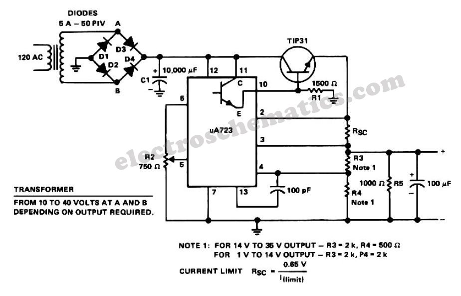
The adjustable power supply can be reconfigured by changing the value of V2 and enhancing other components as needed. The output voltage is calculated using the formula Vnm = 1.25 (1 + R2/R^). Additionally, R2 can be modified as...
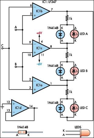
This circuit indicates which of three voltages, ranging from approximately -4V to +4V at points A, B, and C, is the highest by illuminating one of three indicator LEDs. Alternatively, it can be configured to indicate the lowest of...
To operate a car audio or video system from a household 230V AC mains supply, a DC adapter is required. DC adapters available in the market are generally costly. A DC adapter serves as a crucial interface for converting alternating...