
balanced amp

In electronic circuits, signal transmission can be categorized into unbalanced and balanced configurations. Unbalanced circuits, such as those found in simple triode preamps or single-ended amplifiers, utilize a single signal path with a common ground reference. This configuration is straightforward but susceptible to noise and interference, particularly over longer cable runs. The electrical characteristics of unbalanced circuits can lead to distortion, especially in the presence of varying signal amplitudes, as seen in the case of guitar amplifiers, where second harmonic distortion is prevalent.
Balanced circuits, on the other hand, employ two signal paths that are driven in opposite phases. This configuration is advantageous for minimizing noise and interference, as any external noise that couples into the signal paths affects both phases equally and can be canceled out at the output. The use of a phase inverter, which creates two balanced signals from an unbalanced source, is crucial in maintaining signal integrity throughout the amplification process.
In the context of a low-power amplifier design using an EL84 power tube, careful consideration of the output transformer impedance and operating conditions is essential. The choice of an 8k plate-to-plate output transformer allows for efficient operation in Class A mode while ensuring that the components remain within their specified limits. The design aims to achieve a balance between tonal quality and operational efficiency, with the potential for rich harmonic content derived from the interplay of balanced and unbalanced stages in the amplifier. The unique characteristics of this configuration can produce a distinctive sound that is both warm and dynamic, appealing to a wide range of musical styles.Signals always involve at least two paths to complete a circuit. Send some electrons down the center lead of a guitar cable, for example, and you get an equivalent number back on the shield. Because the shaft of the plug is connected to ground at the amplifier jack, we tend to think of its voltage as always zero.
The voltage at the tip of the plug , on the other hand, varies with the signal. This conceptual understanding works fine in most amplifier work. When the voltage at the grid of a 12AX7 triode rises relative to ground we can say with equal authority that ground drops in voltage relative to the grid. The fact that one statement seems scientifically reasonable and the other a sign of imminent psychosis is because of the substantial physical differences between the two reference points.
One is just a tiny pin at the base of the tube socket. The other is a massive steel chassis connected by the power cable to a kilometer of big green wires in the wall. The building`s multi-ampere distribution system connects the power cable to an electrical service panel bonded to a big copper rod that is thrust deep into the earth.
So in effect our planet earth connects your chassis to my test bench, a Vox AC30 warming up in Tokyo, and thousands of other working amps. The send and return path for the signal, in this case the tube pin and the chassis, are physically and electrically different.
The impedances driving them are different. The circuitry connected to them is unsymmetrical. We call this type of signal transmission "unbalanced. " A simple triode preamp is unbalanced. So is a single-ended power amp. When the circuit is symmetrical, like for a pair of power pentodes in push-pull, and when both phases are driven by equivalent impedances, then the circuit is said to be "balanced. " The power tube grids vary with respect to ground in an equal and opposite way. The signal is represented by a difference in voltage between identically configured, mirror-image circuits.
Balance has its advantages. For example, AC ripple in the power supply tends to change the voltage of both signal phases in the same direction. Both phases either increase or decrease together, and since the voltage difference between the phases remains the same, the effects cancel.
For guitar amps there are important harmonic implications. Single-ended amplifiers remain unbalanced through the entire signal path from the guitar to the output transformer. In each stage the amplification factor varies as the signal swings positive and negative, producing second harmonic distortion.
Traditional push-pull amplifiers remain unbalanced through the preamp stages but shift into balanced-mode at the power stage, where equal distortion occurs for positive and negative swings. This tends to cancel even harmonics and create odd harmonics. Balance produces substantially different tonal characteristics. In a push-pull amp, the transition from an unbalanced to a balanced signal path is facilitated by the phase inverter.
It takes an unbalanced signal referenced to ground and creates two balanced signal paths of opposite phase. By moving the phase inverter all the way forward to the guitar input jack, we transform the unbalanced guitar signal into a balanced amplifier signal and create an opportunity to preserve balance through the remainder of the signal chain.
Let`s see how this would work in a low-power design. For my low-power example circuit the EL84 power amp screens are operating at lower voltages than typically seen in a push-pull guitar amp and the plate and screen dissipations are well below their limits. I`m using an 8k plate-to-plate output transformer like a traditional Class AB amp, even though this design is biased to operate in pure Class A mode.
In a high-power, high-fidelity world that would call for reducing the impedance to 4k. The difference between cutoff and saturation is about 12 volts and the DC operati 🔗 External reference
Related Circuits
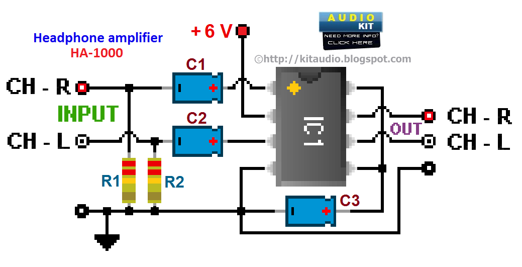
Assembly is straightforward; simply follow the PCB overlay. Ensure that the integrated circuit and the electrolytic capacitors are oriented correctly. The electrolytic capacitors are polarized, marked with a + or - sign, and must be installed properly into the...
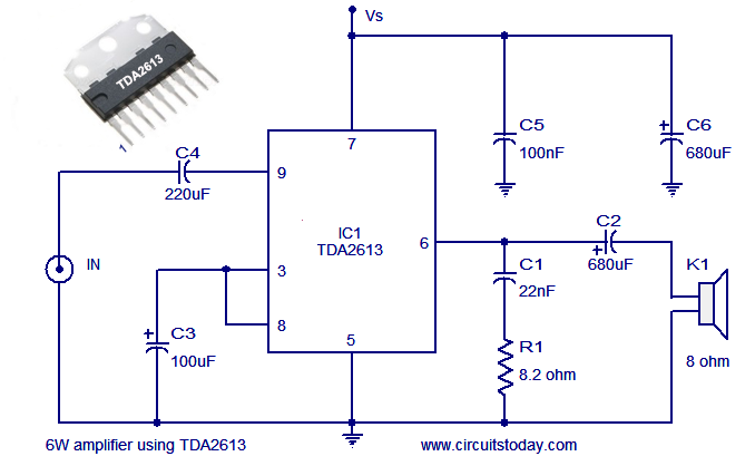
A simple and easy-to-build Hi-Fi audio power amplifier circuit is presented here. This 6-watt Hi-Fi audio amplifier circuit utilizes the TDA2613 integrated circuit (IC). The circuit design employs the TDA2613, which is a high-performance audio amplifier IC known for its efficiency...
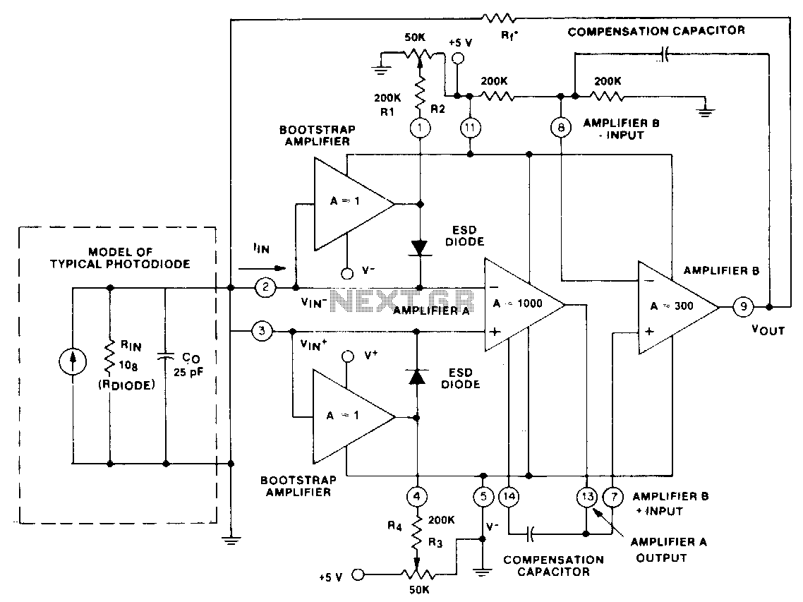
This circuit utilizes a CA5422 dual BiMOS microprocessor operational amplifier. The bootstrap amplifiers reduce bias currents while providing electrostatic discharge protection. Additionally, the potentiometers and their corresponding resistors, R1 through R4, allow the user to adjust bias currents to...
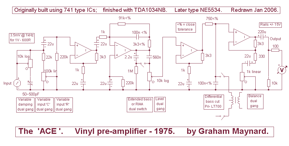
Many designers assert that NFB loop controlled amplifiers are inferior because they degrade the sound. However, it's worth considering what these individuals believe they are actually listening to. The reality is that most vinyl waveforms and CD pits, as part...
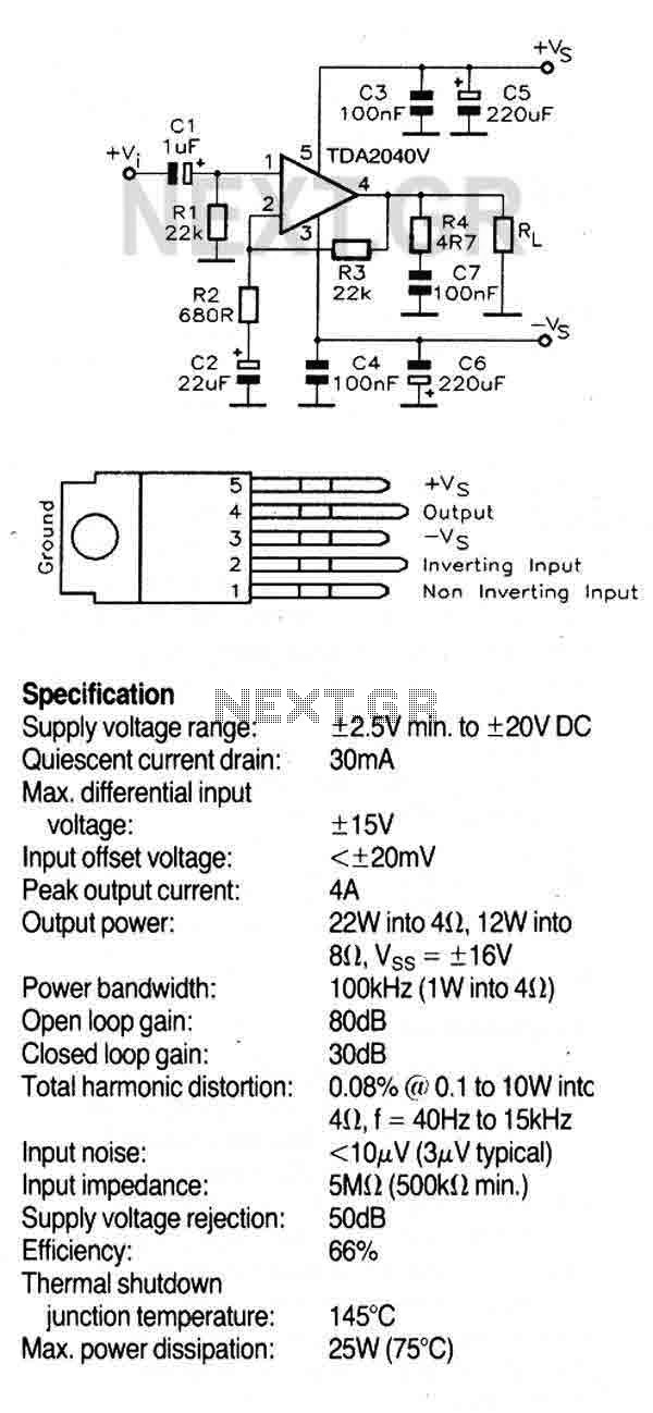
This circuit utilizes the TDA2040V, a monolithic power amplifier integrated circuit designed for high-quality, class AB audio amplification. It typically delivers 22W of output power into a 4-ohm load with a distortion level of 0.5%, powered by a 32V...
The amplifier is 3 dB down at 100 kHz and has a slew rate of 0.02 V/µs. The amplifier's performance characteristics indicate that it experiences a 3 dB attenuation at a frequency of 100 kHz. This specification suggests that at...