
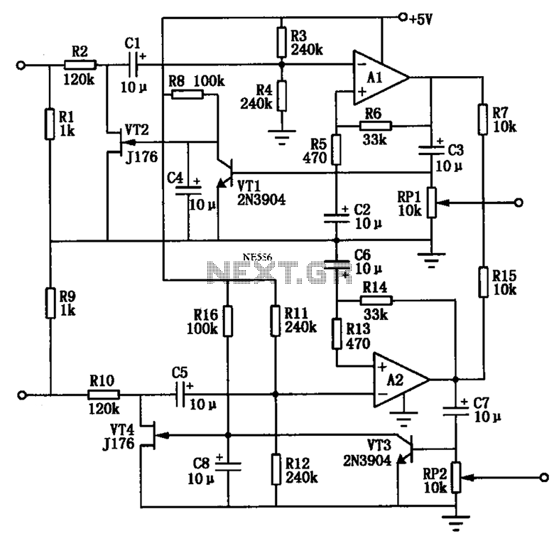
low cost audio headphone amplifier

The assembly process of the circuit board requires careful attention to the orientation of components, particularly the integrated circuit (IC) and electrolytic capacitors. The PCB overlay serves as a visual guide, providing clear markings that indicate the correct placement of each component.
Electrolytic capacitors are polarized components, which means they have a positive (+) and negative (-) terminal. It is crucial to install these capacitors in the correct orientation to prevent damage or malfunction. The PCB will have corresponding markings to assist in this process. Failure to connect the capacitor correctly may lead to short circuits or reduced performance.
The integrated circuit also has specific orientation requirements. The IC and its corresponding socket will typically feature a notch at one end. This notch is a critical reference point that aligns with the PCB layout. If the IC does not have a visible notch, a dot will be present next to pin 1, serving as an alternative orientation marker. Incorrect installation of the IC can result in malfunction or permanent damage to the component.
In summary, following the PCB overlay and paying close attention to the orientation of polarized components such as electrolytic capacitors and integrated circuits is essential for successful assembly. Proper installation ensures the circuit operates as intended and maintains reliability throughout its lifecycle.Assembly is very straight forward, just follow the PC board overlay. Make sure you get the integrated circuit and the electrolytic capacitors the correct way around. The electrolytic capacitors are polarized, they have a + or - marked on them and they must be inserted correctly into the PCB. The IC and socket have a notch at one end, which is mark ed on the PC board overlay. If there is no notch on the IC, there will be a dot next to pin 1, which is the same end. 🔗 External reference
Related Circuits
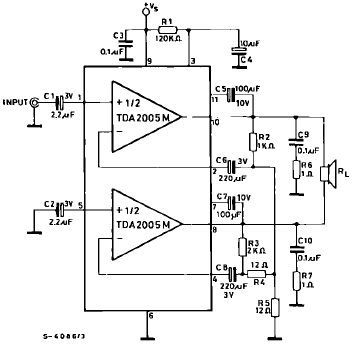
The TDA2005 is a Class B dual audio power amplifier package specifically designed for car radio applications. It facilitates the easy design of car radio power boosters. The TDA2005 power amplifier is engineered to deliver high-quality audio output in automotive...
Electronics tutorial about active low pass filters, including low pass filter frequency response, op-amp voltage gain, and active filter construction. An active low pass filter (ALPF) is an essential component in electronics, designed to allow low-frequency signals to pass while...
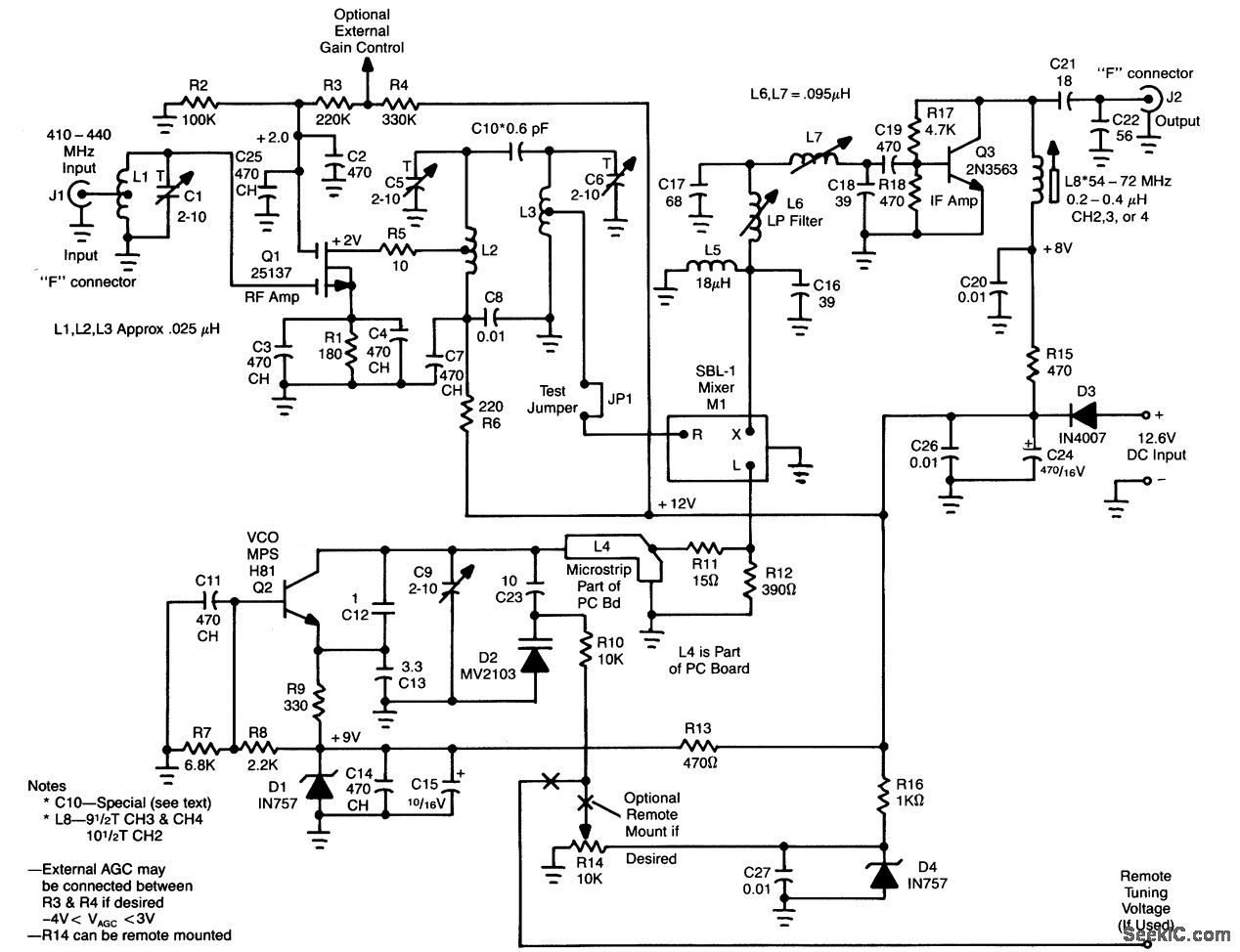
L1, Q1, L2, and L3 form an RF amplifier stage that drives M1, a doubly balanced mixer. Q4 serves as a local oscillator stage operating in the 375-MHz range. Signals in the 420 to 450-MHz range from Q1 are...
This circuit can be directly connected to CD players, tuners, and tape recorders. It requires the addition of a 10K logarithmic potentiometer (dual gang for stereo) and a switch to accommodate various sources. Proper grounding is crucial to eliminate...
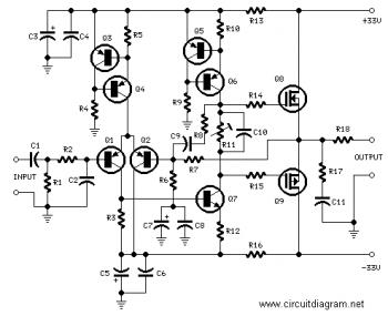
The circuit utilizes two 2N3819 FETs arranged in a cascode configuration. The lower FET functions in common source mode, while the upper FET operates in common gate mode, achieving full high-frequency gain. The lower FET is tunable, enabling peak...
The Audio Automatic Gain Control (AGC) circuit monitors the output signal level of an audio preamplifier. When the input signal increases, the AGC circuit automatically reduces the amplifier's gain. Conversely, when the input signal decreases, the AGC circuit increases...