
Balanced Microphone Preamp
The circuit employs a differential amplifier configuration using compound transistor pairs, specifically the 2N4403 and BC549, to enhance linearity and minimize distortion. The differential input stage allows for the rejection of common-mode signals, making it particularly effective in environments with high electromagnetic interference. The emitters of the transistor pairs are connected to a common mode gain control, which enables adjustment of the overall gain while maintaining the differential nature of the circuit.
The output stage utilizes a high-performance operational amplifier, such as the TL071, configured as a differential gain stage. This op-amp is capable of providing a gain of either six or 15 dB, allowing for flexibility in signal amplification. The maximum input level is set at approximately 1.5 volts RMS, which corresponds to a sound pressure level (SPL) exceeding 150 dB when interfaced with a standard microphone. This characteristic makes the circuit suitable for professional audio applications where high dynamic range is critical.
With a total gain of 1000 times or 60 dB, the circuit demonstrates excellent performance characteristics, including low distortion levels that remain below the noise floor even at high gain settings. The Common Mode Rejection Ratio (CMRR) exceeds 60 dB, ensuring effective hum rejection superior to that of typical microphone cables. This design is ideal for use in mixing desks and other audio processing equipment, where maintaining signal integrity and minimizing noise are paramount.The design consists of differential compound pairs of transistors with a common mode (floating) gain control connecting the emitters of the pair. The compound pairs of 2N4403 and BC549s are far more linear than any single transistor. The circuit is differential in and out and therefore requires a balanced to unbalanced buffer to give suitable output for the next signal stages of a channel in a mixing desk.
This is provided by a high performance op-amp differential gain stage, which can be a TL071 or similar IC of your choice. The stage has a gain of six or 15 dB and that sets the maximum input level at about 1.5 volts rms before clipping.
This equals an SPL of over 150dB with a typical microphone! Full gain is 1000 times or 60dB. Distortion is low to unmeasurable because it is below the noise level at high gains. The CMRR (Common Mode Rejection Ratio) is well over 60 dB and better than any available mic cable as far as hum rejection is concerned. T 🔗 External reference
Related Circuits
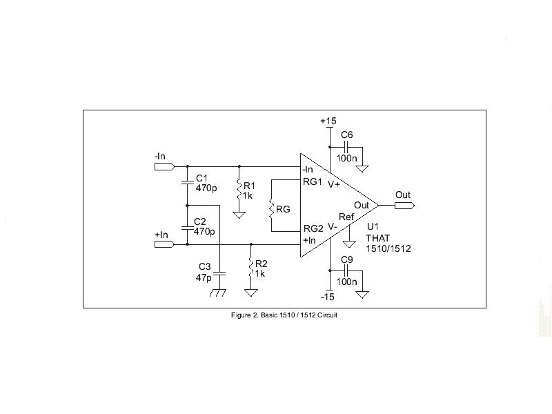
A portable battery-powered microphone preamplifier will be designed using the IC THAT1510. The basic preamplifier circuit provided in the THAT1510 datasheet will serve as the foundation for this project. The proposed circuit will utilize the THAT1510 integrated circuit, which is...

Four high-level inputs, double bar switching. This module can be a necessary addition to the Modular Preamplifier Control Center when more than two sources are required. The described circuit module serves as an interface for connecting multiple audio sources to...
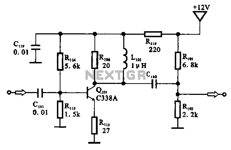
The amplifier circuit is designed as a pre-amplifier configuration. It utilizes transistor Q101 and other components such as inductor L101 and biasing elements. The transistor operates as a common emitter intermediate frequency (IF) amplifier. The IF signal is coupled...
A microphone amplifier that may be used with either Electret Condenser Microphone (ECM) inserts or dynamic inserts, made with discrete components. Both transistors should be low noise types. In the original circuit, BC650C which is an ultra low noise...
Noise in an amplifier circuit is intrinsically generated by each component within the circuit. Resistors, capacitors, and semiconductors all contribute to noise generation. Noise in an amplifier circuit can significantly affect performance and signal integrity. Each component, including resistors, capacitors,...
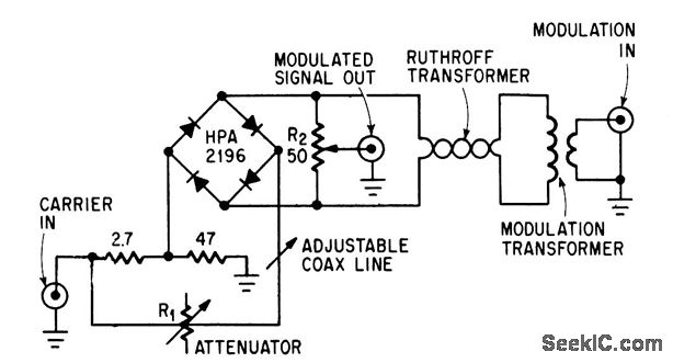
This circuit achieves high carrier and modulation suppression by utilizing closely matched diodes. It includes resistor R1 for amplitude adjustment and a coaxial line for phase adjustment. Resistor R2 allows for slight amplitude adjustments. The described circuit is a...