
TV preamplifier circuit
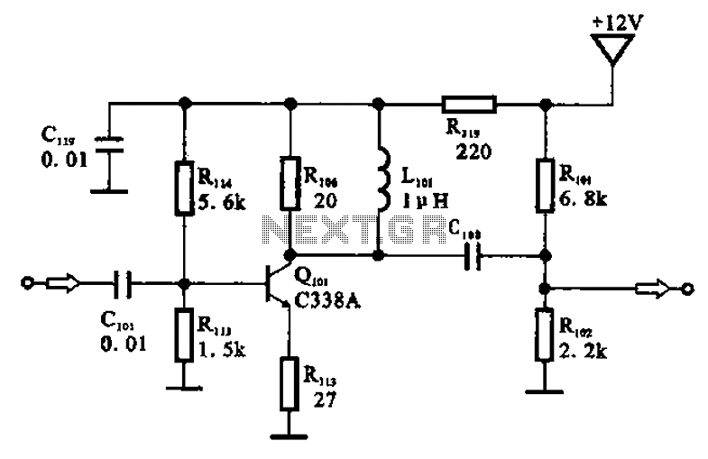
The described amplifier circuit configuration is essential for processing weak signals in various communication applications. The common emitter configuration of transistor Q101 provides significant voltage gain, making it suitable for amplifying low-level IF signals. The coupling capacitors C101 and C103 are critical components in this design, ensuring that DC bias levels do not interfere with the AC signal amplification process.
Capacitor C101 is responsible for coupling the input IF signal to the base of the transistor while blocking any DC offset that might be present. This allows the transistor to operate in its active region, where it can effectively amplify the signal. Similarly, capacitor C103 performs a vital function by preventing any DC component of the amplified output from reaching the SAW filter X101, which is designed to process only the AC components of the signal.
Inductor L101 plays a dual role in this circuit. It not only serves as a part of the collector load but also enhances the overall high-frequency performance of the amplifier. By providing a high impedance path for high-frequency signals, L101 ensures that the amplifier can respond effectively to rapid changes in the input signal, thereby preserving the integrity of the amplified output.
Resistor R106, placed in parallel with the inductor, helps to stabilize the operating point of the transistor and sets the load for the collector, ensuring efficient power transfer and minimizing distortion. The combination of these components creates a robust pre-amplifier circuit capable of handling a wide range of frequencies while maintaining signal fidelity, making it ideal for use in television and other RF applications.Amp circuit as shown in the pre-television. The pre-amplifier circuit is Qioi and other parts of xlol. Q [ol and biasing element is configured as a common emitter IF amplifier, IF signal through a coupling capacitor c] ol Qioi added to the base, is amplified by the collector output, and then through a coupling capacitor C103 is applied to a surface acoustic wave filter XjoJ input device (the coupling capacitor has a DC blocking effect). Inductor Lioi and collector load resistor R106 in parallel Qioi, the use of high-frequency signal L10l high impedance characteristics in the pre-amp to compensate for high-frequency characteristics.
Related Circuits
A simple 3-way crossover, intended for triamping Hi-Fi systems. This is a conventional 12dB / Octave unit, and cannot be expected to have the same performance as a Linkwitz-Riley aligned filter network. It will still be a vast improvement...
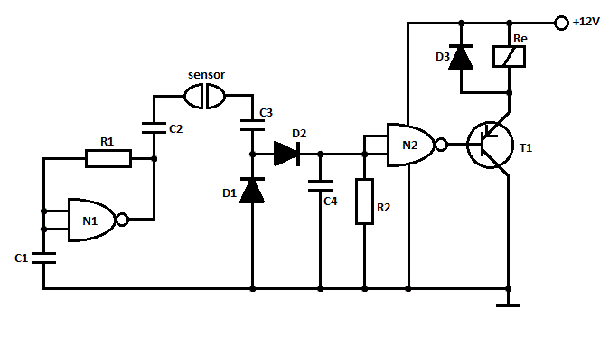
This is a straightforward liquid detector that utilizes a relay to activate an evacuation mechanism. It can be employed for water or any liquid that conducts electricity. Any PNP transistor capable of handling the relay current can be used....
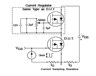
The IRF9540N Gate Charge Test Circuit is illustrated in the diagram below. The IRF9540N is recognized as a rectifier device that employs advanced processing techniques to attain an exceptionally low on-resistance per unit area, as stated in the datasheet....

This is a sensor circuit designed for light detection. It utilizes the LM311 comparator and features a simple design. The comparator is powered by a 12 V DC supply and does not require a negative supply for efficient operation....
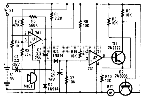
In the circuit, U1 amplifies the audio captured by the condenser microphone. Resistor R1 limits the current, while R2 and R3 center the amplifier's output to a voltage level of %B+ to facilitate the use of a single-ended power...
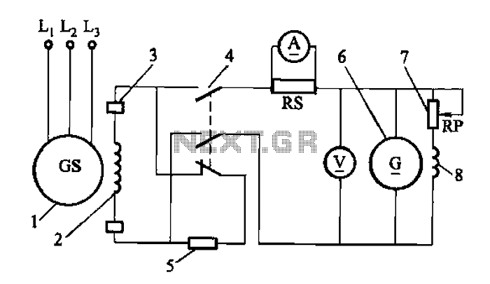
Adjust the exciter field rheostat RP to change the exciter output voltage, which in turn adjusts the generator excitation current, allowing for modifications to the generator output voltage for various purposes. The exciter field rheostat (RP) is a critical...