
Band Pass Filter Tutorial
The passive band pass filter circuit is a fundamental electronic component that allows signals within a specific frequency range to pass through while attenuating signals outside that range. This type of filter is particularly useful in applications such as audio processing, radio communications, and signal conditioning.
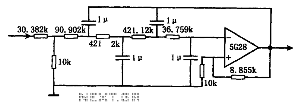
The passive RC band pass filter is typically constructed using resistors (R) and capacitors (C). The first-order frequency response of this filter can be analyzed to understand its behavior in the frequency domain. The configuration generally consists of a series capacitor followed by a resistor connected to ground, creating a high-pass filter effect, which is then combined with a parallel resonant circuit to achieve the desired band pass characteristics.
The frequency response of the passive RC band pass filter can be characterized by two critical frequencies: the lower cutoff frequency (f_L) and the upper cutoff frequency (f_H). The lower cutoff frequency is determined by the resistor and capacitor values, while the upper cutoff frequency is influenced by the reactive components in the circuit. The Bode plot, which graphically represents the gain and phase shift of the filter across a range of frequencies, provides valuable insights into the filter's performance. The plot typically shows a rise in gain at frequencies between f_L and f_H, with a roll-off outside this range.
In practical applications, the design of a passive band pass filter requires careful selection of resistor and capacitor values to achieve the desired frequency response. The quality factor (Q) of the filter, which indicates the selectivity of the filter, can also be adjusted by modifying these component values. Overall, the passive RC band pass filter serves as a crucial element in various electronic systems, enabling effective signal processing and management.Electronics Tutorial about the Passive Band Pass Filter Circuit, including Passive RC Band Pass Filter First Order Frequency Response and Bode Plot.. 🔗 External reference
Related Circuits
A current differencing transconductance amplifier (CDTA) serves as an active component that can be utilized to create various filter responses. The selection of different filter characteristics is achieved by altering the bias current supplied to the amplifier. The current differencing...
The following segment provides the enhanced Motorola schematic for a typical application of the MRF141G, which includes parasitic stabilization features. The MRF141G is a broadband power RF MOSFET capable of delivering a conservatively rated 300 watts across the FM...
The circuit comprises four stages of active bandpass filtering, utilizing two A747 integrated-circuit dual operational amplifiers. It incorporates a simple threshold detector, consisting of diodes D1 and D2, positioned between stages 2 and 3 to minimize low-level background noise....
Separates 130-cps motor drive voltage from voice frequencies in the output of an ADF receiver. P. V. Sparks, Servo Filter and Gain Control Improve Automatic Direction Finder, Electronics, 34:23, p 110-113. The circuit described functions as a filter that effectively...
The circuit illustrated in the figure represents a staggered low-frequency active filter. This is a fourth-order Butterworth low-pass active filter designed to filter very low frequency (VLF) random pulse noise voltage at the DC level. The cut-off frequency is...
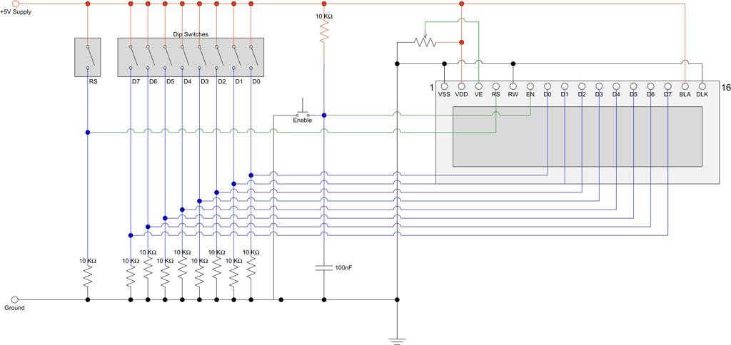
Interfacing with an HD44780 compatible display using DIP switches and a few other components. The module utilized is a 16 character x 2 line display that is in stock. It employs an ST7065C controller, which is compatible with the...