
SYNCHRONOUS FILTER FOR ADF
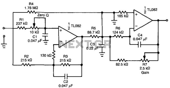
The circuit described functions as a filter that effectively separates the 130-cps motor drive voltage from voice frequency signals present in the output of an Automatic Direction Finder (ADF) receiver. This separation is crucial for ensuring that the motor control signals do not interfere with the audio signals being processed, thereby maintaining clarity and functionality in the system.
The design likely employs a combination of passive and active filtering techniques. A low-pass filter may be utilized to allow voice frequencies to pass while attenuating higher frequency components, such as the motor drive voltage. The filter might consist of resistors, capacitors, and possibly operational amplifiers to enhance the gain and control of the output signal.
The inclusion of a servo filter suggests that feedback mechanisms are in place to stabilize the output, ensuring that variations in the motor drive do not adversely affect the voice frequency output. Gain control circuitry may also be integrated to adjust the amplitude of the filtered signal, providing flexibility in the output level according to the requirements of the subsequent stages in the ADF system.
Overall, the circuit plays a vital role in improving the performance and reliability of the ADF receiver by isolating critical signals and maintaining the integrity of voice communications.Separates 130-cps motor drive voltage from voice frequencies in output of adf receiver-P. V. Sparks, Servo Filter and Gain Control Improve Automatic Direction Finder, Electronics, 34:23, p 110-113.. 🔗 External reference
Related Circuits
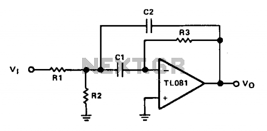
The operational amplifier (op amp) is configured in inverting mode. Resistor R3 connects the output to the inverting input, establishing the gain and the current through the frequency-determining capacitor, C1. Capacitor C2 provides feedback from the output to the...
This circuit is taken from the Progressive Communications Receiver in most of the recent ARRL Handbooks. Values for the 40 meter band are shown. If you want the ultimate in a bandpass filter for 40 or 20 meters, check...
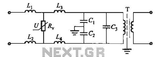
An isolation transformer is connected to a low-pass filter, with specific wiring configurations between them, as depicted in the accompanying figure. The low-pass filter is designed using inductors L1 to L4, which have values ranging from several to several...
By introducing an additional transmission zero to the stopband of a low-pass filter, a sharper roll-off characteristic can be achieved. The filter design example illustrated in Figure 30-1(a) demonstrates that the time-domain performance of the low-pass section can also...
This audio bandpass filter is useful for amplification and filtering of weak AM TV video carriers. For example, a DFM (digital frequency audio multimeter) may have insufficient input sensitivity for measuring extremely weak SSB TV video audio signals. By...

This filter circuit, which utilizes the LM1458 or a similar operational amplifier, has a frequency response ranging from 300 Hz to 3.4 kHz, exhibiting a roll-off of 12 dB per octave outside the passband. Section A serves as the...