
single cdta leads multiple filters
The current differencing transconductance amplifier (CDTA) is a versatile active device widely used in analog signal processing applications. Its unique architecture allows for the implementation of various filter configurations, such as low-pass, high-pass, band-pass, and notch filters. The CDTA operates by converting input current signals into output voltage signals while maintaining high linearity and bandwidth.
In practical applications, the bias current is a critical parameter that influences the performance of the CDTA. By adjusting this bias current, the transconductance parameter of the amplifier can be modified, leading to changes in the filter's cut-off frequency and quality factor (Q). This adaptability makes the CDTA an excellent choice for designing tunable filters that can respond to varying signal conditions.
To implement a filter using a CDTA, the circuit typically includes resistive and capacitive elements arranged to create the desired frequency response. The input current is applied to the CDTA's current input terminals, and the output can be taken from the voltage output terminal. The feedback network, which may consist of resistors and capacitors, determines the filter characteristics, allowing for precise control over the filter's behavior.
In summary, the CDTA's ability to produce multiple filter responses through bias current adjustment, combined with its high performance in signal processing, makes it a valuable component in modern electronic circuit design. Its applications can be found in audio processing, communications, and instrumentation, where flexible and efficient filtering is essential.An active component, a CDTA, can be used as the basis for a variety of different filter responses, selecting the different responses by changing bias current to the amplifier.. 🔗 External reference
Related Circuits
The oscillator was designed to utilize resistors and capacitors instead of large low-frequency LC tank circuits for generating audio frequencies. It achieved low distortion (less than 0.5%) by employing a two-stage amplifier with sufficient negative feedback to set the...
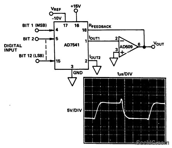
Special tabbed-resistor geometries improve time stability, while full input protection from damage due to static discharge is provided by diode clamps to V+ and ground. Additionally, large IOUT1 and IOUT2 bus lines enhance performance by reducing superposition errors. These...
A bandpass filter allows a specific range of frequencies to pass while rejecting frequencies that fall outside the upper and lower limits of the passband. The frequencies that are permitted to pass are referred to as the passband, which...
This circuit generates a double tone police sound and a single tone old ambulance sound. It is typically installed in battery-powered cars and motorcycles. The circuit utilizes a sound generator IC, such as the 555 timer or a dedicated sound...
The power supply derives its energy from a 24-volt VDC wall adapter, which can be connected through N1, an onboard connector, or N10, an off-board connector. The power switch can be mounted either on the board or off-board via...
Today, simplicity and minimal controls are required for the design of a handheld device. It would be very useful if a circuit allows us to turn the power on or off. A handheld device requires an efficient power management circuit...
Warning: include(partials/cookie-banner.php): Failed to open stream: Permission denied in /var/www/html/nextgr/view-circuit.php on line 713
Warning: include(): Failed opening 'partials/cookie-banner.php' for inclusion (include_path='.:/usr/share/php') in /var/www/html/nextgr/view-circuit.php on line 713