
Bank Harmonic Filters Operation in Power Supply System Cases Studies
The schematic representation of the described power system integrates various components designed to mitigate the negative impacts of non-linear loads on power quality. The primary focus is on the integration of single-tuned and double-tuned filters, which are strategically placed within the circuit to address specific harmonic frequencies generated by the DC drives and arc furnaces.
The single-tuned filters are designed to target specific harmonic orders, such as the 5th harmonic, which is prevalent in systems utilizing 6-pulse rectifiers. The filter design includes inductors and capacitors configured to resonate at the harmonic frequencies, effectively reducing their amplitude in the power system. The parameters of these filters, such as inductance (Lt) and resistance (Rt), are critical in determining their effectiveness and must be calculated based on the system's operational characteristics.
The double-tuned filter further enhances harmonic mitigation by providing a broader frequency response, allowing it to attenuate multiple harmonic orders simultaneously. The configuration includes both series and parallel components, each with distinct resonance frequencies (‰R and ‰S), which are tuned to the specific harmonic frequencies of interest. The interaction between the series and parallel elements creates a complex impedance profile that can be finely adjusted to optimize performance.
The frequency-impedance characteristics depicted in the schematic provide insights into the behavior of the filters under varying load conditions. The analysis includes the equivalent impedance of the power network (ZS) and the combined effects of the harmonic filters (Z2x3h and ZCfilter). This information is crucial for understanding how the filters interact with the overall system and for ensuring that they do not introduce additional resonances that could exacerbate harmonic distortion.
The time-domain characteristics of voltage and current, as well as total harmonic distortion (THD) factors, illustrate the effectiveness of the filters in real-world applications. The graphs showing averaged and maximum values over specified time intervals provide a comprehensive view of the system's performance under different operating conditions.
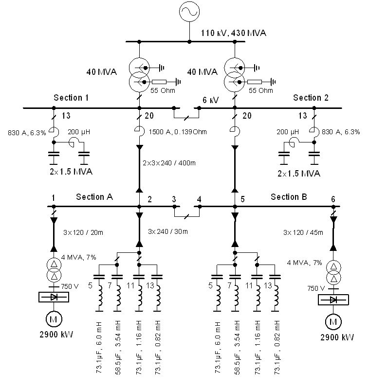
In conclusion, the implementation of harmonic filters within the power system is essential for maintaining power quality, particularly in environments with significant non-linear loads. The careful design and integration of these filters contribute to improved operational efficiency, reduced energy costs, and enhanced reliability of the electrical supply to consumers.The vertical line indicates the instance of the 5th harmonic filter connection Figure 3. Diagram of the power system with the designed group of single-tuned filters for system with DC drive supplied by 6-pulse controlled rectifier:PN = 22kW, UN = 440V, IN = 56, 2A, J = 2, 7kgm2, Rt = 0, 465 ©, Lt = 15, 345mH, nN = 1500 r/min, k = 2, 62 . The voltage-current waveforms and spectrum before and after connecting the filters (U1/I1 basic voltage/ current harmonic; Uh/Ih h. order voltage/current component Figure 9. The double-tuned filter and its essential frequency characteristics;the basic configuration and frequency characteristics of: the series part, parallel part, and the whole filter ( ‰R angular resonance frequency of the parallel part; ‰S angular resonance frequency of the series part; ‰n1, ‰n2 tuned angular frequencies of the double-tuned filter; equation 9 R 0).
Figure 14. Frequency-impedance characteristics of: a) the power network equivalent impedance (ZS), the resultant impedance of two 3rd harmonic filters (Z2x3h), the C-type filter impedance (ZCfilter), the resultant impedance of two 3rd harmonic filters and the C-type filter (ZF); b) the impedance seen from the load terminals: without filters (ZS), the network equivalent impedance and two 3rd harmonic filters impedance connected in parallel (Zs|Z2x3h), and parallel connection of the network equivalent impedance, two 3rd harmonic filters and the C-type filter impedances (Zs|Z2x3h|ZCfilter) Figure 16. Voltage and current characteristics, spectrums and THD factors at 110 kV side. The graphs show two time characteristics: 10 min. averaged values (blue) and 10 ms maximum values (yellow) Figure 17. Current characteristics, spectrums and THDI factors of Arc-furnace and C-type filter. The graphs show two time characteristics: 10 min. averaged values (blue) and 10 ms maximum values (yellow) Figure 18. Current characteristics, spectrums and THDU factors at 30 kV side. The graphs show two time characteristics: 10 min. averaged values (blue) and 10 ms maximum values (yellow) Continuous technological development facilitates the increase in the number of nonlinear loads that significantly affect the power quality in a power system and, consequently, the quality of the electric power delivered to other customers.
DC and AC variable speed drives and arc furnaces are ranked among the most commonly used large power nonlinear loads. DC drives can be a significant plant load in many industries. They are commonly used in the oil, chemical, metal and mining industries. These drives are still the most common large power type of motor speed control for applications requiring very fine control over wide speed ranges with high torques.
Power factor correction is particularly important for this drives because of relatively poor power factor, especially when the motor is at reduced speeds. Additional transformer capacity is required to handle the poor power factor conditions and more utilities are charging a power factor penalty that can significantly impact the total bill for the facility.
The DC drives also generate significant harmonic currents. The harmonics make power factor correction more complicated. Power factor correction capacitors can cause resonant conditions which magnify the harmonic currents and cause excessive distortion levels. For the same reasons arc furnaces are very difficult loads for a supplier and for the customer they are very difficult objects of reactive power compensation and harmonics filtering.
One of the most common methods to prevent adverse effects of nonlinear loads on the power network is the 🔗 External reference
Related Circuits
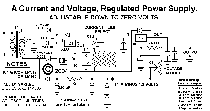
This circuit employs a rotary switch to select various current ranges, as using a potentiometer is not practical for lower resistance and high current ranges. However, a potentiometer can be utilized for lower current ranges, with the lowest switch...
Build a 20 Amp 13.8 Volt Power Supply. There are some electronic applications where it may be necessary to run relatively high current circuits, such as transformers. To construct a 20 Amp, 13.8 Volt power supply, the following components and...
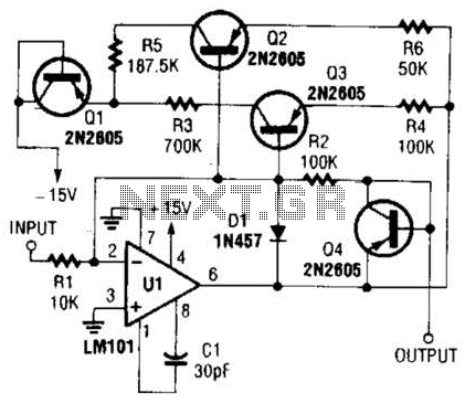
This operational amplifier circuit utilizes resistor and transistor feedback elements to function as a nonlinear amplifier. The resistors R4 and R6 can be adjusted to modify the breakpoints as needed. This operational amplifier circuit is designed to operate within the...
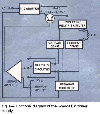
By combining switching and series-pass techniques, the designer of this high-voltage supply achieved 0.01% regulation at power levels up to 100W. The high-voltage power supply employs a hybrid approach that integrates both switching and series-pass regulation methods to achieve exceptional...
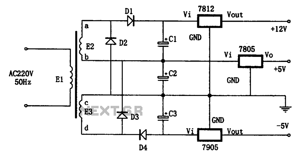
The circuit illustrated in the figure represents a specialized power supply configuration. It is straightforward in design and can be constructed using two identical secondary windings to generate three distinct DC voltage outputs: +5V, -5V, and +12V. The circuit...
This audio amplifier circuit is designed for use in classrooms to alleviate the strain of lecturing in noisy environments. It incorporates the power amplifier IC LM380, which delivers an output of 2 watts, adequate for confined spaces. The amplifier...