
barcode scanner emulator
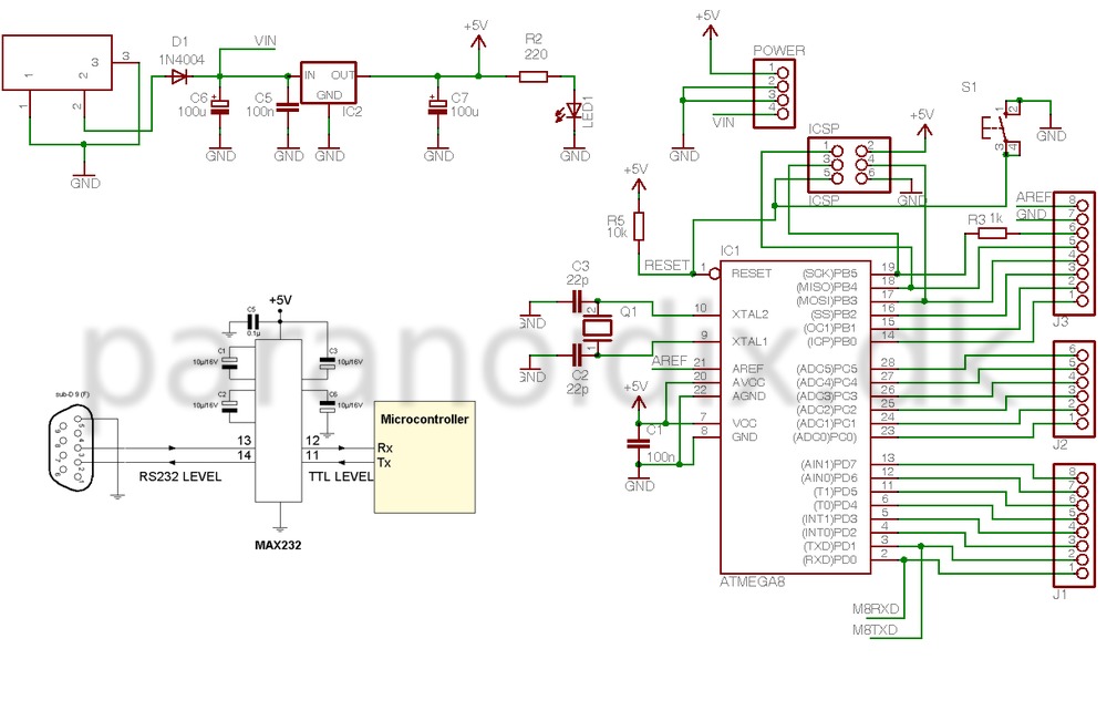
The electronic schematic for this barcode emulator integrates several key components to achieve its functionality. The heart of the circuit is the MAX232 chip, which converts TTL logic levels to RS232 voltage levels, allowing for reliable communication with RS232-compatible devices. The power supply for the circuit is derived from the RS232 port, providing the necessary 5V to power the BAR-X unit, ensuring compatibility with various equipment.
The microcontroller, likely an ATmega series from the Arduino platform, serves as the main processing unit. It is programmed to manage the UART communication, sending ASCII strings corresponding to the barcode data. The program includes functions to initialize the UART settings, send characters and strings, and handle keypad input for triggering specific barcode transmissions. The keypad is configured with three columns and four rows, allowing for multiple input options.
In terms of wiring, the schematic includes connections from the microcontroller's digital pins to the keypad matrix. Each row and column are set as either input or output as necessary, and internal pull-up resistors are enabled for the input pins to ensure stable readings. The LED indicator connected to one of the microcontroller's pins provides visual feedback when a barcode is successfully transmitted.
The code structure is designed for efficiency, employing a loop to continuously check for keypad presses and send the corresponding barcode data. Each transmission is concluded with a CR and LF, ensuring that the receiving device correctly interprets the end of the string. Overall, this schematic represents a practical implementation of a barcode emulator, leveraging widely used components and straightforward programming techniques to achieve its goals.Build primarily as proof of concept and because I found the challenge interresting, this little unit is able to send an ascii string terminated with a CR/LF via a RS232 connection. It`s emulating the transmission of a barcode and can be used with any kind of equipment that is expecting a barcode.
I have been a little lazy on this project, as I hav e based it on the arduino serial V2 layout. This is also the reason I don`t have a neat schematic to show. But I have the reference schematic from the arduino board. And my handdrawn notes on the wiring and keypad. Please note that I have replaced the transistor version of the TTL to RS232 circuit with a MAX232 chip. This makes a more stable signal for the RS232 communication. Oh, and there is also a connection to pin1 on the SUB-D (not shown on the schematic) for supplying the BAR-X with a 5 volt from the RS232 port.
(only available on specific equipment) And finally to make the whole thing work. Here is the sourcecode for the embedded program. Mind you it`s nothing fancy. I tried using some procedures to shorten the code. But it never worked So I took the sequential approach instead. /* * Barcode Emulator V0. 1 * * = * * A pre-defined ASCII code will be send * * using RS232 to a PC or other equipment * * connected via the serial connection. * * A Carriage Return(CR) and * * Line feed (LF) char will be appended. * * = * * Programmed by Rene Rasmussen 2011-09 * * This software released under the GPL * */ #include // define _delay_ms().
// for the delay to work correctly the compiler optimization must be set to -O2 #define UART_BAUD_RATE 9600L #define UART_BAUD_CALC(UART_BAUD_RATE, F_CPU) (F_CPU)/(UART_BAUD_RATE)*16L)-1) // wait ms Milliseconds void delay_ms(uint16_t ms) { uint16_t t; for(t=0; t<=ms; t+) _delay_ms(1); } void uart_putc(unsigned char c) { while(!(UCSRA & (1 << UDRE); // Wait for UDR ready UDR = c; } void uart_puts (unsigned char *s) { while (*s) { uart_putc(*s); s+; } } void uart_ini() { UCSRB |= (1 << TXEN); // Enable UART TX (send) UCSRB |= (1 << RXEN ); // Enable UART RX (receive) UCSRC |= (1< >8); // Choose Baudrate UBRRL=(uint8_t)UART_BAUD_CALC(UART_BAUD_RATE, F_CPU); } void init_keypad() { // Set all keypad outputs (A-D) to HIGH PORTC |= (1<<0)|(1<<1)|(1<<2)|(1<<3); } void main (void) { char CR, LF; // Barcode to be send over RS232 const unsigned char *const barcode[] = { "BARX01", "BARX02", "BARX03", "BARX04", "BARX05", "BARX06", "BARX07", "BARX08", "BARX09", "BARX10", "BARX11", "BARX12"}; DDRC = 0; // reset all bits to zero on port C DDRD = 0; // reset all bits to zero on port D /* Keypad layout * * col 1 2 3 * row * 1 [1][2][3] * 2 [4][5][6] * 3 [7][8][9] * 4 [*][0][#] */ DDRD &= ~(1 << 5); // PD5 set as input (DDRD. 5 = 0) [column 1] DDRD &= ~(1 << 6); // PD6 set as input (DDRD. 6 = 0) [column 2] DDRD &= ~(1 << 7); // PD7 set as input (DDRD. 7 = 0) [column 3] DDRC |= (1 << 0); // PC0 set as output (DDRC. 0 = 1) [row 1] DDRC |= (1 << 1); // PC1 set as output (DDRC. 1 = 1) [row 2] DDRC |= (1 << 2); // PC2 set as output (DDRC. 2 = 1) [row 3] DDRC |= (1 << 3); // PC3 set as output (DDRC. 3 = 1) [row 3] PORTD |= (1 << 5); // PD5 enable internal pull-up PORTD |= (1 << 6); // PD6 enable internal pull-up PORTD |= (1 << 7); // PD7 enable internal pull-up DDRD |= (1 << 4); // PD4 set as output (DDRD. 4 = 0) [LED] PORTD &= ~(1 << 4); // PD4 set to LOW CR = 0x0D; // Carriage Return Code LF = 0x0A; // Linefeed uart_ini(); init_keypad(); while (1) // Loop forever { // Row 1 PORTC &= ~(1<<0); // Set A (DDRC. 0) low delay_ms(50); // delay to allow port to settle if(PIND & (1 << PIND5) = 0) { uart_puts(barcode[0]); uart_putc(CR); uart_putc(LF); while (PIND & (1 << PIND5) = 0) { PORTD |= (1<<4); // activate LED } PORTD &= ~(1<<4); // deactivate LED } if(PIND & (1 << PIND6) = 0) { uart_puts(barcode[1]); uart_putc(CR); uart_putc(LF); while (PIND & (1 << PIND6) = 0) { PORTD |= (1<<4); // activate LED } PORTD &= ~(1<<4) 🔗 External reference
Related Circuits
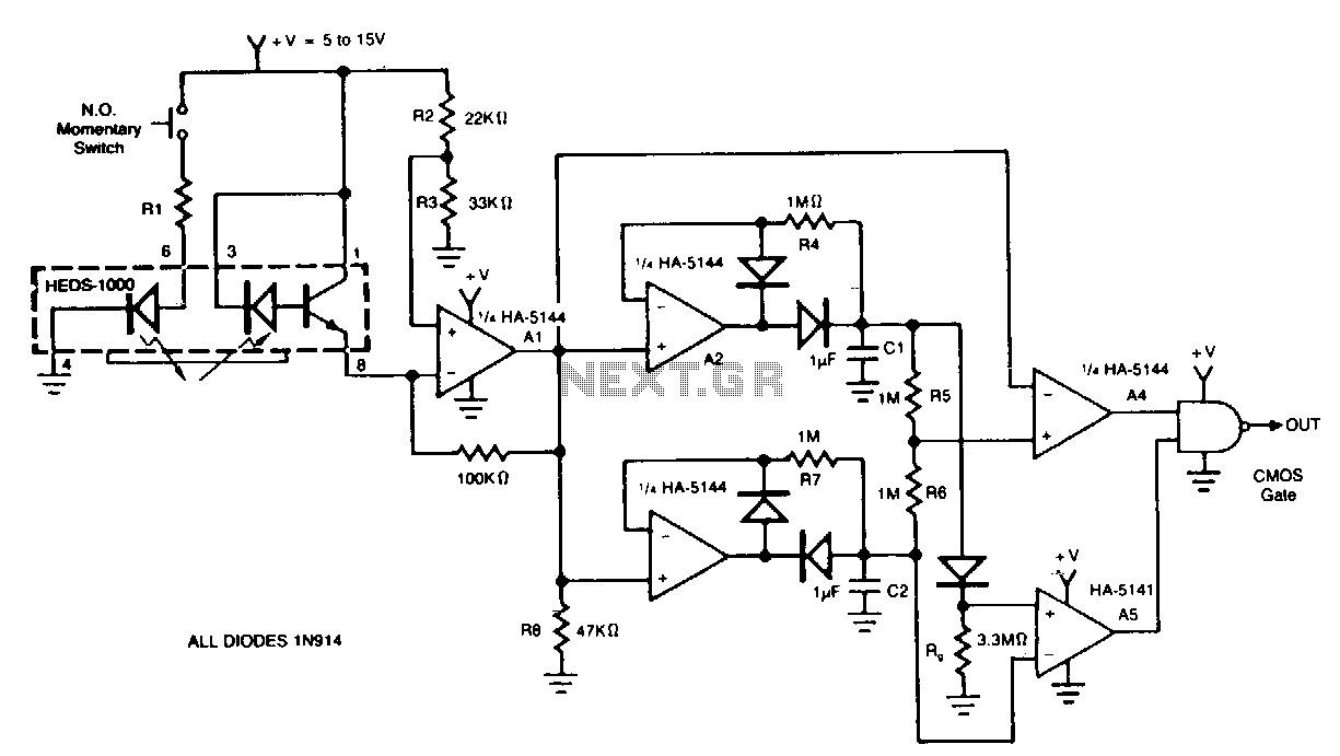
The circuit demonstrates a method for interfacing a HEDS-1000 emitter-detector pair with a HA-5144, intended for use as a barcode scanner circuit. The HA-5144 functions as an amplification system that transforms the widths of the printed barcode's bars and...
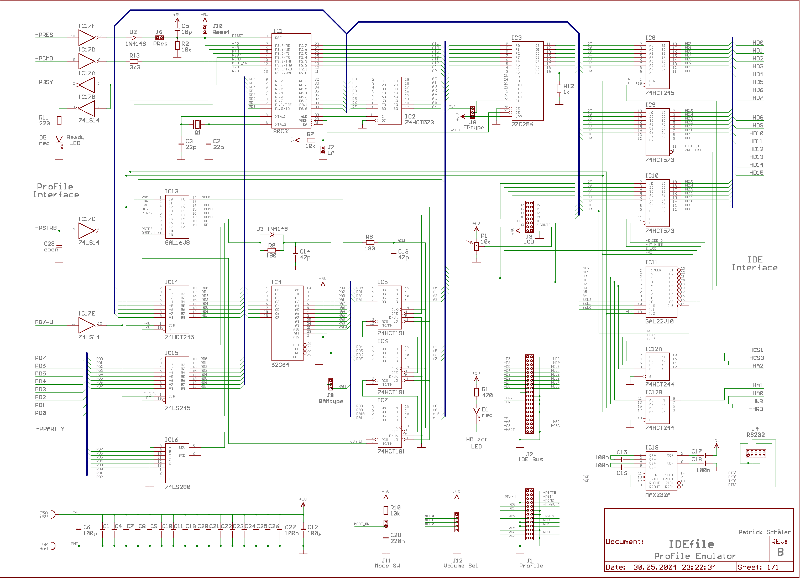
This interface has become a standard for nearly all operating systems known today. IDEfile is a ProFile-compatible hard drive designed for Apple /// and Lisa systems. It emulates the classic 5MB ProFile and the rare ProFile 10M. There are...
This scanner uses a DDS circuit to scan through the frequency band. Since a DDS is used to set the desired frequency, this receiver can jump from one frequency to another within microseconds, making it very fast. The receiver...
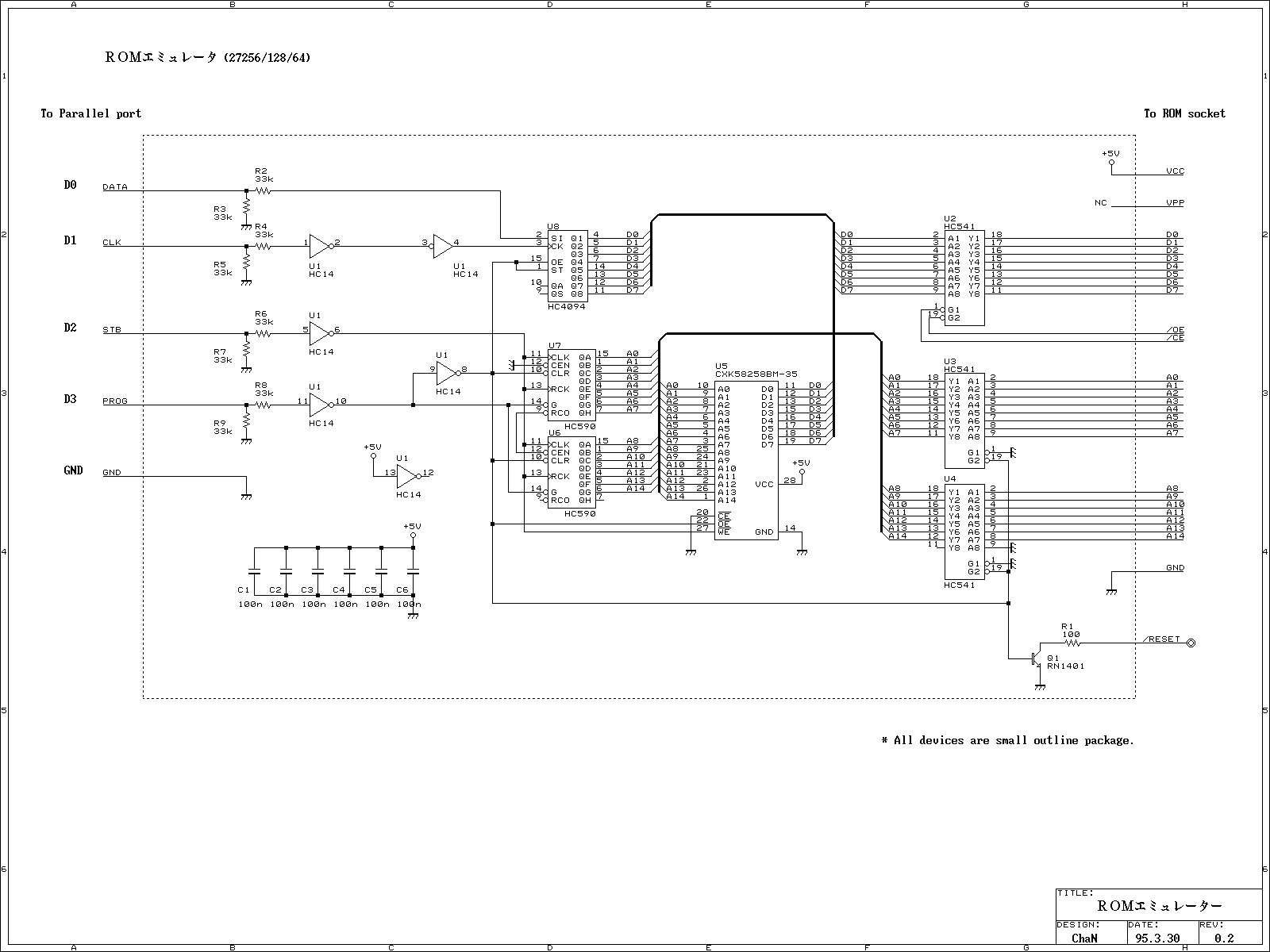
This ROM emulator improves the easiness to build/use it by reducing down its function which can be used as a ROM emulator. The kind of the ROM types to be emulated are 2764, 27128, and 27256. The debugging capability...
The system utilizes the DSP56F826 chip as the primary control module and incorporates a CMOS digital image sensor capable of capturing images with a resolution of 640 x 480 pixels. For applications requiring higher resolution, a chip supporting 1024...
This project Digital gated Emulator using Microcontroller is used to emulate the basic gates such us NOT, OR, AND. The system has the selector switch by which we can select any gate. The system has two inputs and one...