
LED Digital gated Emulator using AT89C2051
The Digital Gated Emulator circuit utilizes a microcontroller to simulate basic logic gates: NOT, OR, and AND. The architecture of the circuit includes a microcontroller unit (MCU), which serves as the central processing unit for interpreting the inputs and controlling the outputs based on the selected logic gate.
The circuit features two Single Pole Double Throw (SPDT) switches that allow for the selection of two input signals, which can be either high (logic 1) or low (logic 0). The state of these inputs is read by the microcontroller, which processes the logic operation based on the selected gate.
A selector switch is incorporated into the design, enabling users to choose which logic gate to emulate. This switch is connected to the microcontroller's input pins, allowing it to determine which gate's logic should be applied to the inputs. The selection of the gate is visually indicated through three dedicated LEDs on the board, each corresponding to one of the gates: NOT, OR, and AND. When a gate is selected, the respective LED illuminates, providing a clear indication of the current operation being performed.
The output of the circuit is represented by a single LED, which signifies the result of the logic operation based on the selected gate and the current input states. The microcontroller executes the logic functions as follows:
- For the NOT gate, the output is the inverse of the input.
- For the OR gate, the output is high if at least one of the inputs is high.
- For the AND gate, the output is high only when both inputs are high.
This setup allows for hands-on experimentation with basic digital logic concepts, making it an educational tool for understanding how these fundamental gates operate within digital electronics. The circuit can be powered by a standard DC power supply suitable for the microcontroller and associated components.This project Digital gated Emulator using Microcontroller is used to emulate the basic gates such us NOT, OR, AND. The system has the selector switch by which we can select any gate. The system has two inputs and one output. We use two SPDT switches for the inputs and for the output we use an LED. The gate selection can be done by the selector switch and it is also indicated on separate LEDs. There are three LEDs provided on the board for the gates NOT, OR, AND. The corresponding LED will glow for the corresponding gate. The main op 🔗 External reference
Related Circuits
The project involves installing LED strips in a car's tail lamps to replace conventional bulbs. The required lengths for the LED strips are 16 inches, 15 inches, and 14 inches to fit properly within the housings. The selected LED...

This single-cable system transmits composite video (NTSC, PAL, or SECAM), power, and channel selection signals. The interface end of the circuit delivers 10 V down the cable, pulses the supply voltage to transmit channel-change commands, and buffers the received...
Humanity has long grappled with the concept of Time, often seeking ways to interact with it meaningfully. A proposed solution is a knocking platform designed to address these fundamental needs, exemplified by the Knock Block KUI and its associated...
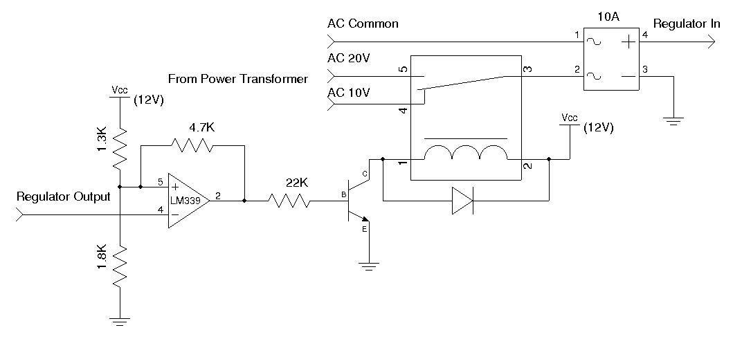
A used 250VA power transformer has been removed from equipment recently. The transformer features a dual 10V AC output along with several auxiliary voltage outputs. The 10V winding is rated for 10A, making it suitable for a high current...
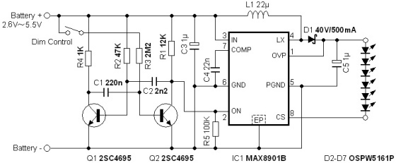
The circuit illuminates a high-brightness LED even at a voltage of 0.8V if the battery can supply 93mA at this voltage. The average step-up efficiency from 0.8V to 1.5V is 75%, with a peak efficiency of 83% occurring around...
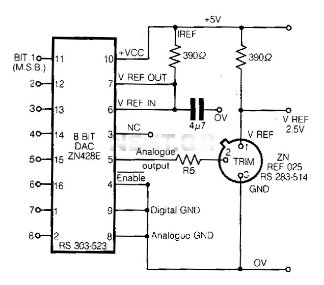
This circuit demonstrates a straightforward approach to achieving a voltage reference that can be adjusted using an 8-bit Digital-to-Analog Converter (DAC) equipped with an integrated voltage reference. The analog output from the DAC controls the trim pin of the...