
Based CNC programming gain instrumentation amplifier PGA202 203 schematic

The PGA202/203 series of programmable gain amplifiers are designed for high-performance applications requiring precise signal amplification. These integrated circuits offer a wide range of programmable gains, typically from 1 to 1000, making them suitable for various sensor signal conditioning tasks in CNC systems.
The circuit diagram for the PGA202/203 involves the following key components:
1. **Power Supply**: The amplifier requires a dual power supply, typically ±5V to ±15V, to allow for proper signal amplification without clipping.
2. **Input Stage**: The input stage consists of differential inputs (V1 and V2), which are connected to the source of the signal to be amplified. This configuration helps in rejecting common-mode signals, thereby enhancing the accuracy of the measurement.
3. **Gain Setting Resistors**: The gain of the PGA202/203 can be adjusted using external resistors connected to the gain pins. These resistors set the feedback loop, determining the overall gain of the amplifier. The gain can be programmed through a digital interface in some configurations, allowing for dynamic adjustments based on the application requirements.
4. **Output Stage**: The output of the PGA202/203 is a single-ended output that provides the amplified signal. This output can drive further processing stages or be connected to an analog-to-digital converter (ADC) for digitization.
5. **Filtering**: It is often beneficial to include low-pass filters at the input and output stages to minimize noise and enhance the signal integrity, particularly in high-frequency applications.
6. **PCB Layout Considerations**: Careful attention should be paid to the PCB layout to minimize parasitic capacitance and inductance, which can adversely affect the performance of the amplifier. Proper grounding and power supply decoupling are essential to maintain stability and reduce noise.
Overall, the PGA202/203 instrumentation amplifier circuit is a versatile solution for amplifying low-level signals in CNC applications, providing high accuracy and flexibility in gain settings. Based CNC programming gain instrumentation amplifier PGA202/203 circuit diagram as follows:
Related Circuits
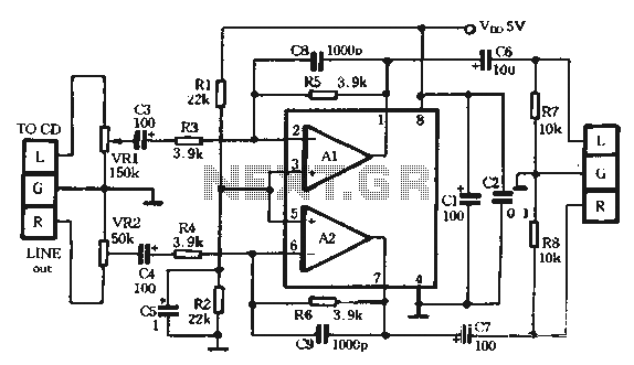
The TDA1308 is a Class AB headphone driver integrated circuit (IC) recently launched by Philips. Its primary features include a compact size and low power consumption, making it particularly suitable for portable CD players and other digital audio devices....
The TDA2003 offers enhanced performance while retaining the same pin configuration as the TDA2002. It maintains the advantageous features of the TDA2002, including a minimal number of external components, ease of assembly, and savings in both space and cost....
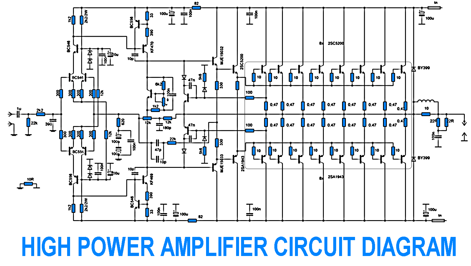
700W Amplifier. Adjusting the amplifier power to 700W appears straightforward, yet it is essential to consider the adjustment of the driving transistors and the frequency offset engagement. It is necessary to modify the current protection circuit that safeguards the...
In terms of AC signals, the base is connected to the ground through capacitor C3. Consequently, both the input and output are linked to the base, forming a common base amplifier configuration. The common base amplifier is a type of...
24V DC is a widely used voltage in industrial environments. The circuit illustrated below is designed to accept four different 24V DC alarm input signals, which are utilized to activate a single low-power beeper. The beeper is a magnetic...
Since I have provided the schematic for John L Linsley-Hood's Class-A amplifier, I felt that some readers may wish to experiment with the concept. Unfortunately, a very low ripple power supply is needed for all Class-A amps, and the...