
Transistor Common Base Amplifier

The common base amplifier is a type of transistor amplifier where the base terminal is common to both the input and output circuits. This configuration is particularly useful for applications requiring high-frequency response and low input impedance. The input signal is applied to the emitter terminal, while the output is taken from the collector terminal.
In this setup, the capacitor C3 serves as a coupling capacitor, allowing AC signals to pass while blocking DC components. This ensures that the DC biasing conditions of the transistor remain stable, which is critical for maintaining linear amplification.
The common base amplifier typically exhibits a voltage gain greater than one but provides a low input impedance, making it suitable for matching with low-impedance sources. Additionally, the output impedance is relatively high, allowing for effective signal transfer to subsequent stages of amplification.
When designing a common base amplifier, careful consideration must be given to the biasing network, which usually consists of resistors connected to the emitter and collector to set the operating point of the transistor. The choice of transistor type (BJT or FET) will influence the amplifier's performance characteristics, including gain, bandwidth, and linearity.
Overall, the common base amplifier configuration is an essential part of electronic circuit design, particularly in RF applications, where its unique properties can be leveraged for effective signal processing.As far as AC is concerned, the base is connected to the ground by the C3. Therefore, both input and output are connected to the base (common base amplifier).. 🔗 External reference
Related Circuits
The prototype was successfully assembled on a breadboard and subsequently built on a piece of Radio Shack protoboard for field use. The assembly process took only a couple of hours, and it functioned correctly on the first attempt. This...
The System Monitor feature discussed in this article was successfully utilized by Avalon Microelectronics in two Virtex-5 FPGAs (XC5VLX330T) during their development. They encountered an unusual issue where the development board would shut down while the FPGAs were executing...

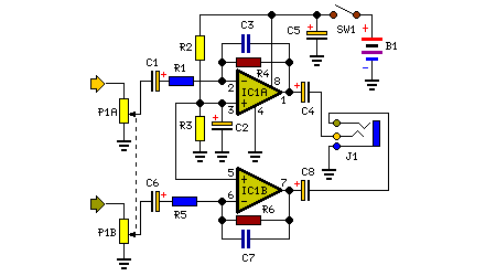
The preamplifier circuit is designed to offer appropriate loading for phono cartridges with reluctance. It achieves a gain of approximately 25 dB at 1 kHz (converting an input of 2.2 mV to an output of 100 mV). The circuit...
The decision to design a 9V powered headphone amplifier has been finalized. The primary requirement was to power the circuit using a common PP3 (transistor radio) alkaline battery. The introduction of the 5534 low-noise op-amp at a reasonable price...
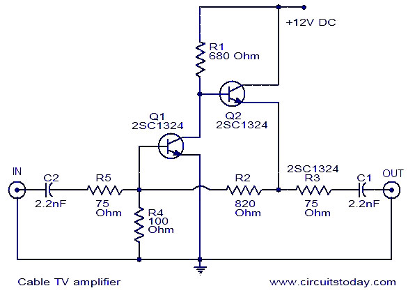
This is a simple cable TV amplifier using two transistors. The amplifier circuit is designed for cable TV systems utilizing 75 Ohm coaxial cables and is effective up to 150 MHz. Transistor T1 is responsible for amplification, providing up...
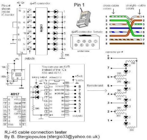
Vasilis Stergiopoulos has developed an RJ45 LAN cable tester. The circuit was initially designed to utilize a 555 timer and a 4017 decade counter IC, but Vasilis has released a schematic and assembly source code for implementing the Attiny2313...