
Beeper & Buzzer Schematics
The circuit design encompasses multiple functionalities that can be adapted for various applications, including alarm systems, sirens, and notification devices. The use of the 555 timer is prevalent due to its versatility in generating precise timing pulses and oscillations. The incorporation of diodes to create an OR gate facilitates the combination of multiple input signals, allowing for a robust alarm system that responds to any triggered input.
The LTC1799 frequency generator is noteworthy for its precision in generating stable frequencies, which is essential for applications requiring accurate timing such as sirens and alarms. The 74HC14 Schmitt trigger enhances signal integrity, ensuring that the output is clean and free from noise, which is particularly important in digital circuits and when interfacing with analog components.
The design also emphasizes power efficiency, particularly in battery-operated devices, where the low idle current and visual indicators for low voltage conditions are critical for maintaining functionality without frequent battery replacements. The piezo alarm circuit demonstrates the potential for high sound output while maintaining compactness, making it suitable for applications where space is a constraint but loud alerts are necessary.
Overall, this comprehensive circuit description illustrates the versatility and adaptability of electronic components in creating efficient alarm and notification systems, catering to both industrial and consumer applications.24v DC is a very popular voltage used in industrial settings. The circuit below was designed to accept four different 24v DC alarm input signals, which are then used to drive a single low power beeper. The beeper is a magnetic type with its own oscillator/driver. The four diodes form an OR gate so any one of the four inputs will cause the beeper to make noise. A CMOS version of the popular 555 timer is used to strobe the beeper on and off at about 1Hz. 3V Sweeping Siren Alarm - The circuit uses a LTC1799 precision frequency generator from Linear Technology. A 74HC14 hex Schmitt trigger from Texas Instruments is also used to perform several other functions. One section is wired as a simple 7Hz square wave oscillator. 555 Tone Generator 8 Ohm Speaker - This is a basic 555 square wave oscillator used to produce a 1 Khz tone from an 8 ohm speaker.
In the circuit on the left, the speaker is isolated from the oscillator by the NPN medium power transistor which also provides more current than can be obtained directly from the 555 (limit = 200 mA). A small capacitor is used at the transistor. American Police Car Siren (linscott) - Scroll down to locate this circuit. The 555 on the right is wired as an alarm tone generator and the second 555 timer on the left is wired as a low frequency astable timer which generates a ramp waveform of about 6 seconds that is buffered by the transistor and again used to frequency modulate the tone generator.
The transistor is used to help strengthen the signal to the speaker. Another Very Loud Piezo Alarm Beeper - This is yet another beeper circuit that really draws attention. It sweeps the drive frequency slightly to produce a very annoying sound. It uses a transformer to increase the drive voltage across the piezoelectric device to more than 200 volts peak to peak.
It cranks out an ear splitting 120db when measured at 12 inches. Automotive & Household Siren Driver Circuits: Zsd100 & Discrete `H`-Bridge Minimum Parts Count Solution - Zetec Semiconductors Applications Notes A solution is provided that uses a minimum number of components by utilizing an application specific signal generation IC, and a high efficiency `H`-bridge effected with 3A DC rated Super- TO92 style switching transistors. Basement Doorbell Beeper - If you can`t hear your doorbell when you are in your basement try this circuit.
This circuit takes advantage of the 24vac power source located near the furnace. Using a simple current transformer technique, the circuit sounds a beeper whenever the main door chime is activated. Battery Low Voltage Beeper - This circuit provides an audible and visual low voltage warning for 12V battery powered devices.
Idle current: 6ma Low Voltage Warning current: 15ma Beeper Bug This bug can be attached to anything from a glider to a plant and you can track it with a radio. Why track a plant The Beeper is the result of many requests for a mini tracking device and introduces a new world of tracking British Police Car Siren - The first circuit simulates the siren of a British police car.
It uses two 555 timers in the circuit. The 555 on the right is wired as an alarm tone generator and the second 555 timer on the left is a 1 Hz astable multivibrater. Click Sound Generator - Often in computer controlled systems, you would like to generate a click sound whenever a button is pressed.
This provides the user with audible feedback that the pushbutton press has been acknowledged. The two circuits below generate such a sound. A click sound is generated each time the logic input swings from a logic low to high condition. Continuity Buzzer is Frugal with Power - EDN-Design Ideas: [Note: File contains multiple circuits. Scroll to find this one] The continuity detector in Figure 1 is based on W Dijkstra`s "Fleapower circuit detects short circuits" (EDN, July 2, 98, pg 122). The buzzer indicator allows y 🔗 External reference
Related Circuits
Q1 and Q2 create an ALL-ON ALL-OFF circuit that, when in the off state, draws negligible current. P1 initiates the circuit, activating the relay and powering the two integrated circuits (ICs). The lamp is energized through the relay switch,...
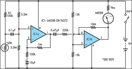
Strictly speaking, this simple circuit should not work. How could anyone expect an ordinary light-dependent resistor (LDR) photocell to detect the change in blood flow as the heart pulsates through a fingertip in natural daylight? The secret lies in...
Using a magnetic compass, ensure that both pickups have a South polarity on the top of each pickup. Verify this by checking for a North polarity on the bottom of the pickups. It is uncommon to find both pickups...
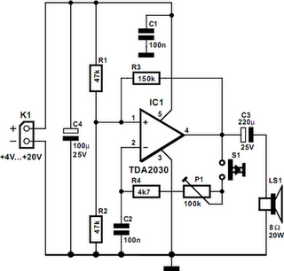
A powerful buzzer in the room, combined with a pushbutton at the bottom of the stairs or in the kitchen, could be very useful in such situations. The core of this circuit is formed by IC1, a TDA2030. This...
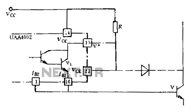
Anti-saturation devices have been removed from the UAA4002 routine applications. The base current of the switching transistor, which is driven by another transistor, is automatically adjusted. This adjustment allows the power transistors to operate in critical saturation. However, when...
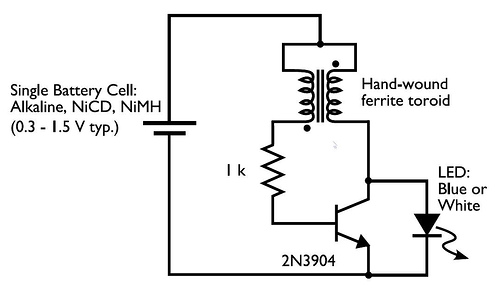
In the circuit diagram for the Joule Thief, the common point of the toroid is the connection at the top of the hand-wound ferrite toroid, located in the upper right of the diagram. This connection leads to the positive...