
Basic 2051`s Circuit
The circuit described utilizes the 89C2051 microcontroller, which is a member of the 8051 family of microcontrollers. This microcontroller is commonly used in embedded applications due to its versatility and ease of integration. The circuit is designed for simplicity, employing point-to-point soldering techniques on a universal printed circuit board (PCB), which allows for flexibility in layout and component placement.
The microcontroller is seated in a standard 20-pin dual in-line package (DIP) socket, which facilitates easy replacement and connection. It is important to note that a circle-pin socket should not be used, as it may not provide reliable connections for the microcontroller's pins.
In the circuit, D1 is represented as a small dot LED, which serves as a visual indicator for the circuit's operational status. The LED's anode is typically connected to a positive voltage, while the cathode is connected to a current-limiting resistor that ensures proper current flow and prevents damage to the LED.
Power regulation is handled by U2, which can be either a 7805 voltage regulator or a 78L05. Both of these components are linear voltage regulators that provide a stable +5V output, suitable for powering the 89C2051 microcontroller and other peripheral components. The choice between the two depends on the current requirements of the circuit, with the 78L05 being suitable for lower current applications.
An optional component, U3, is included in the design to correct any polarity issues that may arise from the DC power adapter. This feature is particularly useful in preventing damage to the microcontroller and associated components if the power supply is connected with reverse polarity.
Before inserting the 89C2051 microcontroller into the socket, it is crucial to verify the integrity of the connections. This can be done by measuring the voltage between pin 20 (Vcc) and pin 10 (GND) of the socket, ensuring that a +5V supply is present. This step is essential to confirm that the power supply is functioning correctly.
To test the LED functionality, a simple procedure involves shorting the P1.7 pin to ground (GND). This action should illuminate the LED, indicating that the microcontroller's output pin is functioning as intended. This testing method is a straightforward way to ensure that the circuit is correctly assembled and operational before proceeding with further development or programming of the microcontroller.A basic circuit of the 89C2051 shown here can be made easily using point-to-point soldering with a universal PCB. Use an ordinary 20-pin socket, do not use a circle-pin socket. D1 is a small dot LED. U2 can be either 7805 or 78L05. U3 is optional for correcting any polarity DC adapter. Without the 2051 chip in the socket, checks the connection, then measures +5V between pin 20 and pin 10. Test the LED by shorting P1.7 pin to GND. 🔗 External reference
Related Circuits
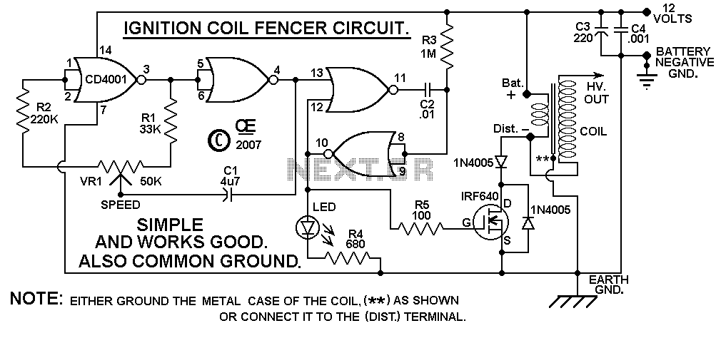
A circuit design based on a C-MOS chip to drive a car ignition coil. This is a very simple and efficient design for an electric fence. It puts out a very high voltage current pulse, yet it draws a...
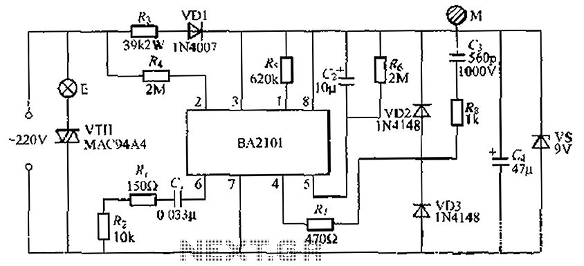
The BA2101 is a dimming controller utilizing an ASIC to create a barrel of light touch stepping. It is a non-constant lamp suitable for heir light. Each touch on the electrode sheet M can adjust the lamp brightness through...
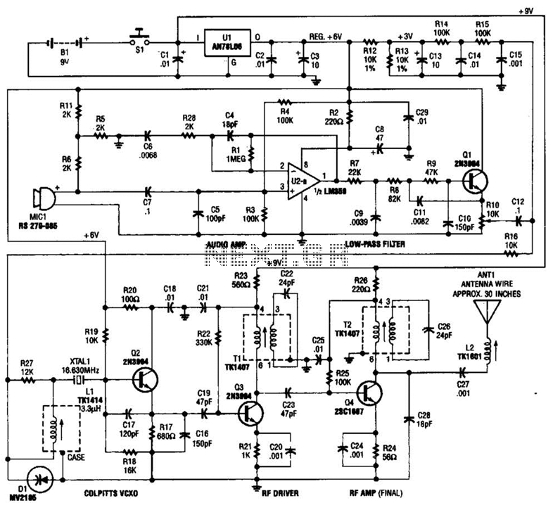
This tracking transmitter consists of four distinct subassemblies: a free-running multivibrator, a transmit switch, an audio-tone generator, and an FM transmitter. The multivibrator, which produces a pulse width with a pulse separation of 1500 ms, is built around Q1...
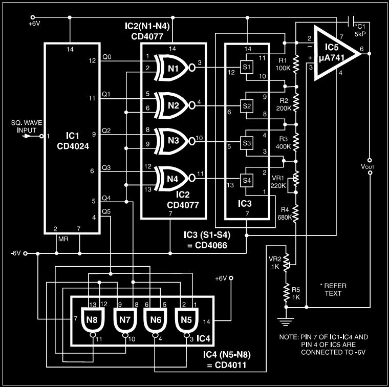
Many electronic devices rely on the shape of signals. Generating square wave signals from sine waves is relatively straightforward, while the reverse process is more challenging. The static square wave-to-sine wave converter circuit can produce an accurate sine wave...
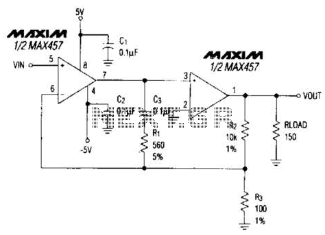
A composite amplifier can be constructed that offers high gain, wide bandwidth, and good DC accuracy by cascading the sections of a dual video amplifier and incorporating two suitable phase compensation components. The operational amplifier drives a 150-ohm load...
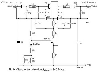
The circuit is designed for driving small UHF TV transmitters, providing a gain of 7 dB and capable of amplifying signals within the frequency range of 470-860 MHz. Key components include resistors, capacitors, and transistors. This circuit serves as a...