
TV RF Amplifier 5W Circuit With BLW98
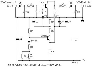
This circuit serves as a critical amplifier stage in UHF TV transmitter applications, enhancing the strength of received signals to ensure optimal transmission quality. The gain of 7 dB indicates that the circuit effectively increases the power level of the input signal, making it suitable for broadcasting within the specified frequency range of 470-860 MHz.
The design typically incorporates a combination of resistors, capacitors, and transistors. Resistors are employed to set the biasing conditions for the transistors, ensuring they operate efficiently in the active region. Capacitors may be used for coupling and decoupling purposes, allowing AC signals to pass while blocking DC components, thus maintaining signal integrity.
Transistors, which are the primary active components in this circuit, function as the amplifying devices. Depending on the specific design, different transistor types (such as BJTs or FETs) can be utilized to achieve the desired performance characteristics. The choice of transistors will influence the overall efficiency, linearity, and thermal stability of the amplifier.
Additional considerations in the design include impedance matching to ensure maximum power transfer from the source to the load, as well as filtering components to minimize unwanted harmonics and noise. The overall layout of the circuit is crucial in minimizing parasitic capacitances and inductances, which can adversely affect performance at UHF frequencies.
In summary, this circuit is an essential component in enhancing UHF TV transmission, utilizing a well-thought-out arrangement of resistors, capacitors, and transistors to achieve a reliable gain and effective signal amplification.Function: for driving small UHF TV transmitters, with gain is 7dB and can amplify a signal between 470-860 MHz. Component: Resistor, Capacitor, Transistor, .. 🔗 External reference
Related Circuits
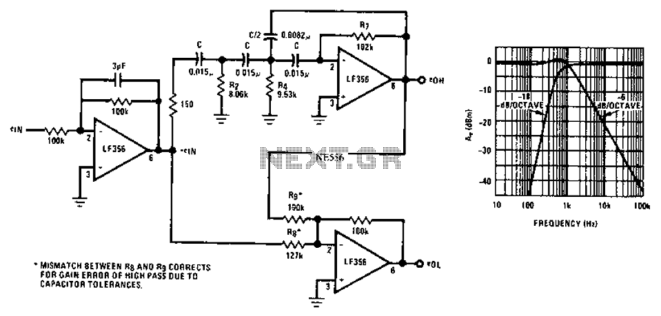
Asymmetric third-order Butterworth active crossover network circuit diagram. The asymmetric third-order Butterworth active crossover network is a sophisticated circuit designed to split an audio signal into two separate frequency bands, typically for use in multi-way speaker systems. This type of...
The monostable 555 timer multivibrator circuit, also known as a one-shot monostable multivibrator, functions as a retriggerable pulse generator. The term "monostable" indicates that the circuit has only one stable state, with the unstable state referred to as the...
TV video signal processor circuit. The ECG1064 chip includes a primary video amplifier, two sync pulse amplifiers, a look-out protector, a noise detector, two noise gates, an automatic gain control (AGC) detector, an intermediate frequency (IF) AGC amplifier, a...
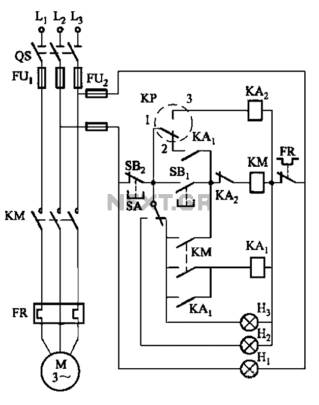
An air compressor is commonly utilized in electrical equipment factories and is typically controlled by electrical contacts. The circuit diagram is depicted in Figure 5-1. The circuit allows for both automatic and manual operation. In the diagram, KP represents...
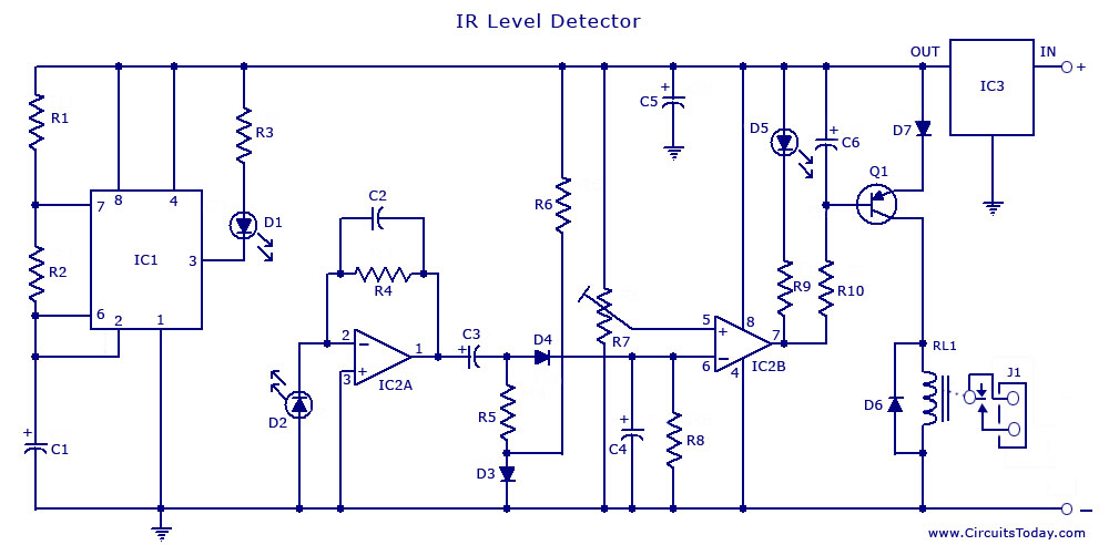
An infrared (IR) sensor or detector circuit diagram utilizing a 555 integrated circuit (IC), primarily employed as a water level or liquid level sensor and proximity detector circuit. The described circuit employs a 555 timer IC configured in a monostable...
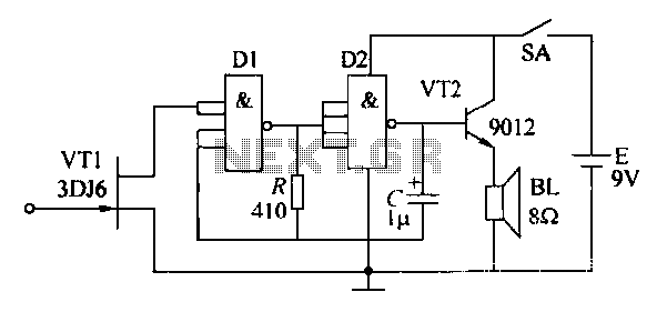
High pressure alarm with high sensitivity. It detects high-voltage electric energy from 10kV at a distance of 2m or from low-voltage mains (AC 220V) at a distance of 0.3m. The alarm device is simple to manufacture, compact, and user-friendly....