
basic equaliser
The TLC272CP circuit design offers a unique approach to audio equalization, emphasizing smooth transitions across frequency ranges. The shunt-feedback configuration ensures effective signal processing with minimal distortion, while the adjustable filters allow for tailored audio output. The implementation of RC networks for boost and cut adjustments ensures both low-pass and high-pass filtering capabilities, facilitating a flexible response that can adapt to various audio requirements.
In practical applications, the circuit can be integrated into audio processing systems for radios, mixers, or other audio equipment where sound quality is paramount. The careful selection of capacitor and resistor values influences the performance characteristics, allowing engineers to optimize the frequency response for specific audio environments. The use of high-quality components will further enhance the circuit's efficiency, ensuring reliable operation and superior audio fidelity.
Additionally, when designing the PCB layout for this circuit, attention must be paid to the placement of components to minimize noise and interference. Proper grounding techniques and shielding may be necessary to maintain signal integrity, especially in environments with high electromagnetic interference. The use of bypass capacitors near the power supply pins of the TLC272CP can further stabilize the operation by filtering out high-frequency noise.
Overall, the TLC272CP circuit exemplifies an effective solution for audio equalization, combining flexibility, efficiency, and high-quality sound reproduction.The second section of the TLC272CP is connected in a shunt-feedback configuration for medium-high input impedance and low output impedance. The gain of this circuit is fixed near unity. Separate boost/cut RC-feedback networks are connected in parallel to form the adjustable low pass and high pass filters.
The crossover frequency of the two filters is approximately 800 Hz when the low end and high end controls are rotated to the same setting. The crossover frequency increases when the low end control is advanced further. When the high end control is adjusted higher than the low end setting, the crossover frequency is decreased. The parallel low pass and high pass resistor and capacitor networks are connected between the. 1 Mfd coupling capacitor from the preamp and the 110 Mfd output capacitor. Refer to the diagram. The two 10K resistors connected to IC pin #6 are signal coupling resistors and are not components that determine frequency response in either the low pass or high pass filtering circuit.
When both controls are in their center positions, the response of the equalizer stage is flat. When set at either end of the control travel, the boost (or cut) causes a change in frequency response of 3 to 4 dB per octave. By adjusting the two filter controls, the audio output can be tailored to a flat, boosted or tilted response.
At the output, the 110 Mfd non-polarized capacitor is formed by two 220 Mfd capacitors connected in series. negative to negative. These series capacitors are connected in series with a 620 ohm resistor (not shown) and pass both high and very low frequency output signals from the EQ to the transceiver input.
It also functions to block any dc voltage that might be present from the transceiver microphone input pin that is present on some transceivers. The TLC272CP operational amplifier operates well within the 5 to 8 supply voltage range that is normally available from most transceivers.
Being a CMOS device, the current drain requirement from the transceiver is very low and virtually insignificant. The low and high end voice response curve of this two-band unit is exceptionally smooth and pleasing to the ear.
The smooth slope in the response from the low end to mid-frequencies and the smooth slope from mid-frequencies to the high end is the key to its excellent performance. This is because the design incorporates a low-pass and high-pass filter rather than utilizing multi-band-pass active-filters (tuned circuits) as in other EQ designs.
These multi-band EQs have an unavoidable overall response curve with many hills and valleys that are associated with its many tuned circuits. This lack of smoothness in its response negatively affects the natural sound character of the voice. There is a fundamental technical reason for these hills and valleys and it is not totally associated with the operators set-up adjustments.
The explanation is related to how the phase shift of the audio voltage and current is affected when its frequency falls between (and within) the response curve of two adjacent tuned circuits (one tuned above the other). Each circuit will shift the voltage-to-current relationship up to a maximum of + or - 90 degrees. The "+" or "-" shift depends on whether the frequency falls above or below resonance. The degree of shift depends on how near or how far it is spaced frequency wise from each of the tuned circuit`s resonant frequency.
The greater the spacing the greater the phase shift. With the multi-band EQ, each pair of adjacent band-pass tuned circuit will shift the phase "+" in one and "-" in the other (when audio falls in between their resonant frequencies). Because the two phase shifts are in opposition, maximum audio cancellation will result when the audio frequency is spaced equally between the two tuned circuits and a lesser amount when the audio frequency is spaced nearer one than the other.
The end result are unavoidable valleys in 🔗 External reference
Related Circuits
This circuit is a simplified version of a commercial uninterruptible power supply (UPS). It delivers a constant regulated 5 Volt output alongside an unregulated 12 Volt supply. In the event of a power failure, the battery seamlessly takes over,...
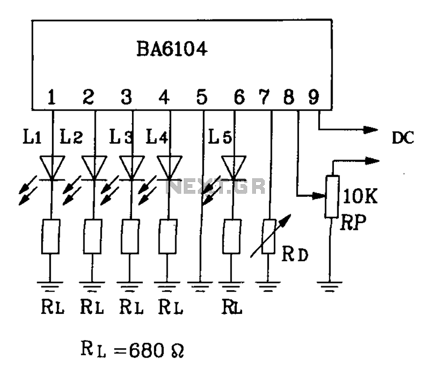
BA6104 is a five-digit LED level meter driver integrated circuit (IC) that features a basic application circuit. The input stage employs a PNP transistor with a composite base input, resulting in high input impedance. The output stage is configured...
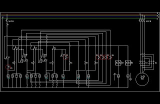
This is a basic lift circuit. When the P1 push button is pressed, the lift starts operating from the 1st floor to the 2nd floor. After a specified time duration, it automatically moves to the 3rd floor. The same...

R4 prevents the output voltage from drifting toward one of the supply rails of the operational amplifier. It is understood that R4 should have a high resistance, although the reason for this is unclear. The schematic appears to be...
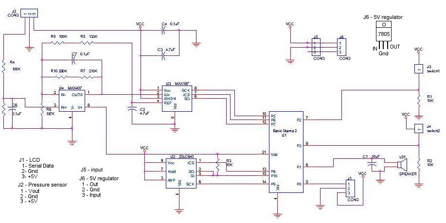
A method for determining altitude involves the use of barometric pressure; however, it presents certain challenges. The relationship between pressure and altitude is not linear but rather complex, a concept developed by the army in the 1930s. The equation...
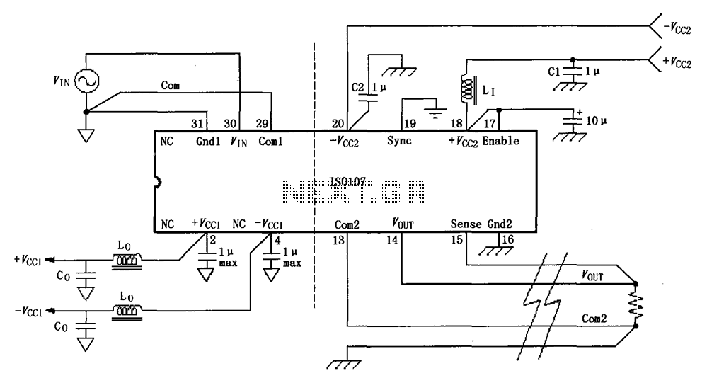
The basic connection circuit for the ISO107 signal and power supply is illustrated. Each power supply terminal must include a bypass filter. If the output current from the isolated power supply exceeds 15 mA, it is advisable to utilize...