
basic lift circuit four floors
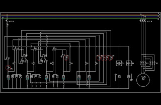
The lift circuit operates using a series of interconnected components designed to facilitate vertical movement between floors in a building. The primary control element is the P1 push button, which initiates the lift's movement. Upon activation, a relay or motor driver circuit is engaged, powering the lift mechanism to ascend from the 1st floor to the 2nd floor.
The circuit may include a timer, which is crucial in determining the duration the lift remains at each floor. This timer can be implemented using a microcontroller or a simple RC timing circuit, depending on the complexity required. Once the timer elapses, a signal is sent to the lift control system, prompting it to engage the next relay or motor driver to continue the lift's journey to the 3rd floor.
Upon reaching the 3rd floor, the same process is repeated. The lift remains at this floor for a predetermined time before automatically moving to the 4th floor. This cycle of operation ensures that the lift is user-friendly and efficient, minimizing wait times for passengers.
Additional safety features may include limit switches that prevent the lift from exceeding its designated floors and emergency stop buttons that can be activated in case of malfunction. Power supply considerations must also be addressed, ensuring that the circuit can handle the load requirements of the lift motor while maintaining safety standards.
Overall, this basic lift circuit exemplifies a straightforward yet effective design for vertical transportation within a multi-story building.This is basic lift circuit. when press P1 push button lift starts to work 1st floor to 2 nd floor. Then after time duration it is automatically reach to 3 rd floor. And samething happen in 3rd floor & 4 th floor. 🔗 External reference
Related Circuits
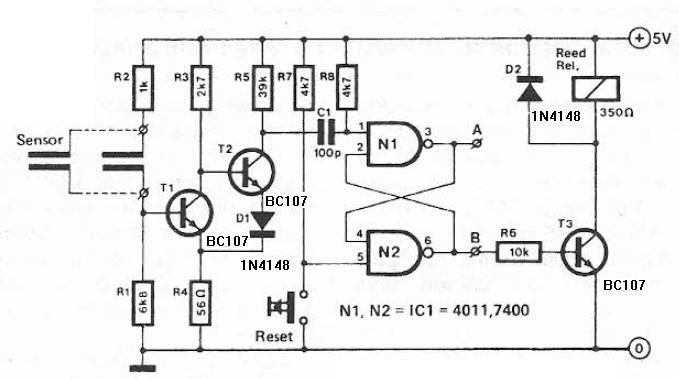
Humidity detector circuit electronic project using common electronic parts The humidity detector circuit is a project designed to measure and indicate the level of humidity in the environment. This circuit utilizes commonly available electronic components, making it accessible for hobbyists...

The schematic includes programmable AVRs. For other members of the AVR family or additional programmable ICs compatible with Ponyprog, there is a J1 connector (CON10) that facilitates hardware expansion of the programmer. Additional information about compatible ICs can be...
This circuit is designed to signal the exceeding of a fixed threshold in room noise through a flashing LED. Three fixed levels are selectable: 50, 70, and 85 dB. Two operational amplifiers provide the necessary gain for sounds captured...
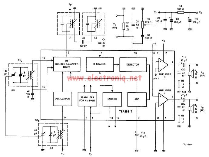
The TEA5551T monolithic integrated radio circuit can be utilized to design an AM radio receiver circuit intended for portable use with headphones. This circuit incorporates all necessary components for a complete AM radio receiver, including a fully integrated AM...
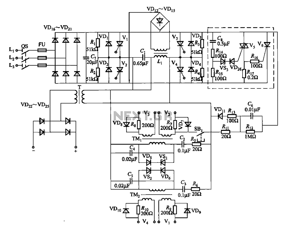
A 25kHz thyristor inverter welding machine circuit utilizes high-frequency operation to enable smaller transformer designs. The circuit diagram is illustrated in Figure 9-14. The no-load output voltage of the machine is 45V DC, with a peak voltage of 90V...
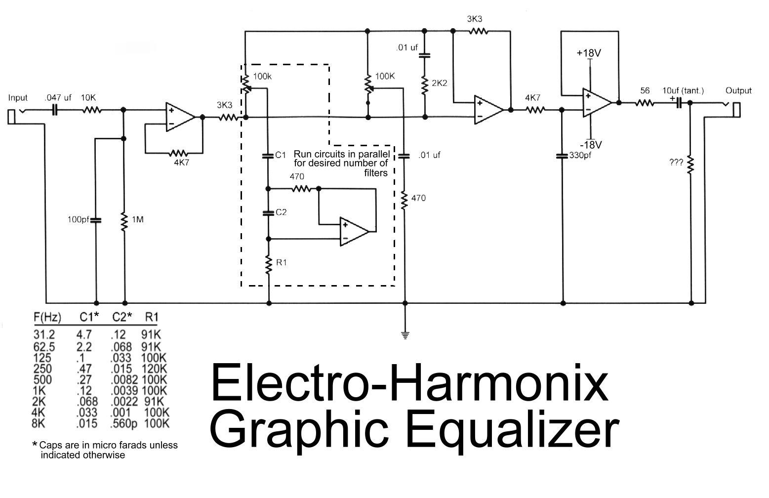
This is the diagram of the Electro-Harmonix graphic equalizer. The number of channels can be specified according to requirements by paralleling the components: C1, C2, R1, an operational amplifier, potentiometer, and a 470-ohm resistor. The frequency to be boosted...