
op amp Basic Frequency Control Circuit

The circuit in question involves an operational amplifier (op-amp) configured with feedback through resistor R4. The primary function of R4 is to provide a DC feedback path, which is crucial for maintaining stability in the output voltage. High resistance in R4 is necessary to ensure that the feedback does not excessively load the op-amp output, allowing it to respond to minor fluctuations in the input signal without significant distortion.
When R4 is present, it creates a negative feedback loop that allows the op-amp to correct any deviations in the voltage at node b. If node b experiences a positive drift, the op-amp can reduce its output, which in turn lowers the voltage at node b, pulling it back toward ground. Conversely, if node b drifts negatively, the op-amp increases its output to counteract this drift. This feedback mechanism is essential for maintaining linear operation within the op-amp's range, preventing the output from reaching the supply rails, which could lead to saturation and potential circuit malfunction.
In the absence of R4, the op-amp operates in open-loop mode, where it cannot effectively regulate the output based on the input. This results in a situation where any drift in node b will lead to an uncorrected shift in the output voltage, causing the op-amp to drive toward one of the supply rails. The open-loop gain of the op-amp, which is typically very high, exacerbates this issue, as even small changes in the input can lead to significant output changes.
Therefore, the inclusion of R4 not only stabilizes the circuit but also enhances the linearity and performance of the op-amp by ensuring that it remains within its operational limits. Proper selection of R4's resistance value is critical, as it must be high enough to avoid excessive loading while still providing adequate feedback to maintain control over the output voltage.R4 prevent the output voltage drifting towards one of the supply rails to the op amp I understand that R4 has to have a high resistance but I do not know why That looks like a Circuit Lab schematic! It would be great if you could post a link to the schematic so that answerers could edit, highlight, and reconfigure it if necessary.
Kevin Vermeer May 14 `12 at 18:13 I love Circuit Lab, but for some reason I cannot save anything I have drawn on it. Otherwise I would, any suggestions on how to save and I would gladly post a link user1083734 May 15 `12 at 8:30 I`ve since found out that the save functions aren`t supported by the Chrome I`m using, I will post a link once I have redrawn using Firfox user1083734 May 15 `12 at 8:59 With R4 removed, there is no DC feedback path from the op-amp output to the input. So if the b node drifts away from ground, there`s nothing the op-amp can do to drive it back towards ground (which it will try to do to keep the two inputs equal).
If b drifts high, the output will tend to rail negative, and if b drifts low the output will tend to rail positive, according to the open-loop gain of the op-amp. With R4 in place, you have a DC feedback path. If b drifts high, the op-amp output can go a little bit low and pull it back to ground. If b drifts low, the op-amp output can go a little bit high and pull it back to ground. 🔗 External reference
Related Circuits
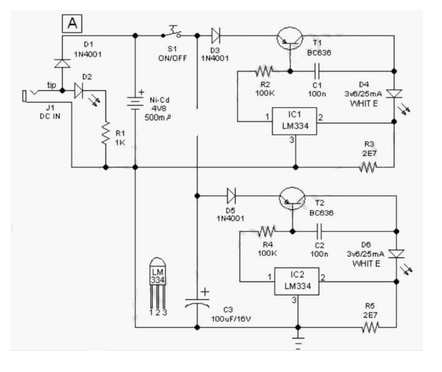
This easy-to-construct "Handy Pen Torch" electronic circuit has a low component count and utilizes two power white LEDs for lighting. It operates on a low voltage supply of 4.8V DC. The Handy Pen Torch circuit is designed to provide a...
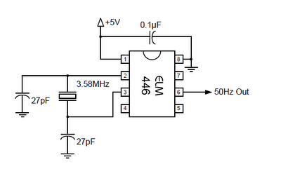
The ELM446 is an 8-pin digital divider integrated circuit that generates both 50Hz and 1Hz outputs from a common 3.58MHz NTSC colorburst crystal. The designer needs to supply only the crystal and two suitable loading capacitors, along with a...
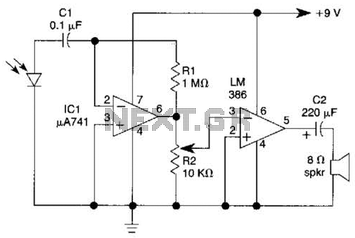
This light-wave receiver comprises a 741 operational amplifier functioning as a preamplifier and an LM386 operational amplifier serving as a power amplifier. The gain control is managed by a potentiometer labeled R2. Various types of detectors can be utilized...
The principle utilized in this electronic head or tail circuit is straightforward: a multivibrator controls a flip-flop. The multivibrator oscillates as long as the button S1 is pressed, while the flip-flop toggles on and off at a frequency of...
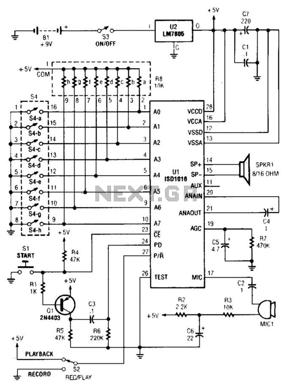
The personal message recorder is based on the ISD1016 CMOS voice messaging system, eliminating the need for complex and costly analog-to-digital and digital-to-analog conversion circuits. A functional block diagram of the ISD1016 is available. The ISD1016 integrates all necessary...
The LM3886 is an improved version of the LM3875. Key features of the LM3886 include a maximum output power of 68W RMS and 108W peak, with a total harmonic distortion (THD) of 0.03% at 60W. The LM3886 is a high-performance...