
Basic Multivibrator

The described circuit operates as a relaxation oscillator utilizing an operational amplifier (op-amp), specifically the TL071, which is known for its low noise and high-speed performance. The fundamental operation relies on the feedback mechanism and the charging/discharging behavior of the capacitor C, which plays a crucial role in determining the oscillation frequency and duty cycle.
The configuration begins with the op-amp's output voltage V0 transitioning to a positive value, driven by the natural offset voltage inherent in the op-amp devices. This positive output is fed back through resistors R2 and R1, creating a positive feedback loop that reinforces the output state until it reaches saturation. The saturation point is contingent upon the supply voltages provided to the op-amp, typically defined by the power supply rails.
As V0 charges capacitor C through resistor R3, the voltage across C increases until it reaches a threshold where the inverting input of the op-amp exceeds the voltage at the non-inverting input. This condition triggers a rapid change in the output state of the op-amp, shifting from positive saturation to negative saturation. The transition results in the capacitor beginning to discharge, effectively lowering the voltage at the inverting input until it aligns with the level of the non-inverting input.
This oscillatory behavior continues as the capacitor discharges through R3, and once the voltage across C drops to the level of the non-inverting input, the op-amp output swings back to positive saturation. The cycle then repeats, generating a square wave output at V0. The timing characteristics of the oscillation can be influenced by the values of R1, R2, and R3, as well as the capacitance of C, allowing for tuning of the frequency and duty cycle.
In summary, the described circuit exemplifies a simple yet effective relaxation oscillator design, leveraging the properties of an op-amp and passive components to achieve a stable oscillation with a balanced duty cycle, facilitated by the characteristics of the TL071 operational amplifier. When this circuit is turned on, the natural offset of the devices serves as an automatic starting voltage. Assume that output voltage V0 goes positive and the positive feedback through R2 and RI forces the output to saturate. The high-voltage level at V0, then charges C through R3, until the voltage at the inverting input exceeds that at the noninverting input.
As the inverting input exceeds the noninverting input level, the output switches to the negative saturation voltage. This action starts the capacitor discharging toward the new noninverting input level. When the capacitor reaches that level, the op amp switches back to the positive saturation voltage, and the process starts again.
With the TL071, the positive and negative output levels are nearly equal, which results in a 50% duty cycle.
Related Circuits
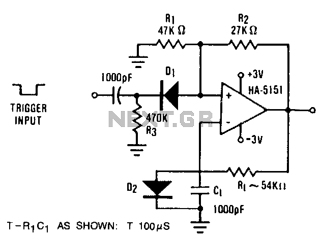
The circuit demonstrates the functionality of the HA-5151 as a battery-powered monostable multivibrator. In this configuration, the time constant is set to 0.632, simplifying the time constant equation to T = R1 * C1. Diode D2 is employed to...

The simplest power supply voltage regulator can be created with the 78xx series. The voltage regulator is available in different voltages (see table). The controller is 100 mA, 1 or 2 A provides. C2 is a decoupling capacitor. He...
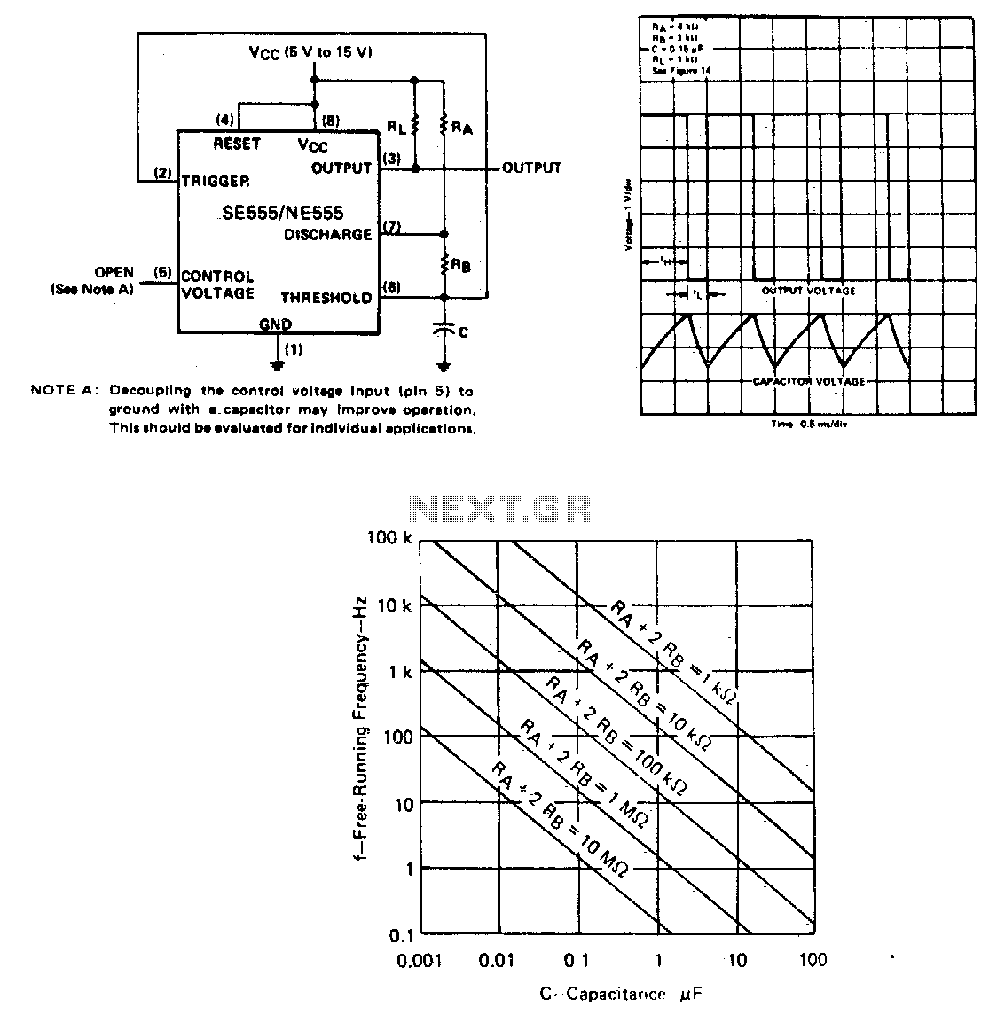
The capacitor C will charge through resistors Ra and Rb, and then discharge through resistor Rb only. The duty cycle may be controlled by the values of Ra and Rb. In this circuit configuration, a capacitor (C) is utilized to...
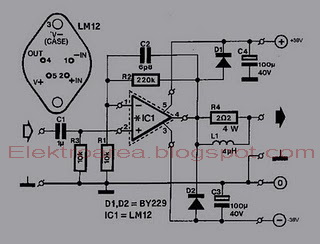
This is an 80W power amplifier OCL circuit that utilizes the integrated circuit LM12. It effectively enhances bass and treble performance. When connected to a CD player, it produces high-quality sound, especially when paired with a good pre-tone control....
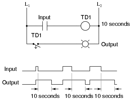
A monostable multivibrator is exemplified by the pulse detector within flip-flop circuitry, which briefly enables the latch portion during clock signal transitions. This device is classified as monostable due to its single stable state, which can maintain its output...
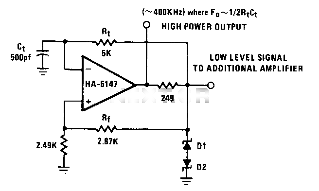
The power bandwidth of the HA-5147 extends the circuit's frequency range to approximately 500 kHz. Resistor R can be made adjustable to vary the frequency if desired. Any timing errors due to Vas or hu have been minimized by...