
Astable multivibrator
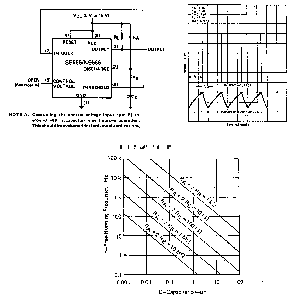
In this circuit configuration, a capacitor (C) is utilized to store electrical energy, which is managed through two resistors (Ra and Rb). During the charging phase, the capacitor receives current through both resistors, Ra and Rb, thereby influencing the time it takes to reach its maximum voltage. The values of these resistors play a crucial role in determining the charging rate, as the time constant (τ) of the RC circuit is defined by the equation τ = R_total × C, where R_total is the equivalent resistance seen by the capacitor during charging.
Once the capacitor is fully charged, it enters the discharging phase, where it releases its stored energy solely through resistor Rb. This configuration allows for a distinct control over the discharge time, as the discharge time constant is given by τ_d = Rb × C. The ability to adjust the values of Ra and Rb provides flexibility in managing the duty cycle of the circuit, which is the ratio of the time the capacitor spends in the charging phase to the total period of the cycle. By changing the resistance values, one can effectively modify the duration of both charging and discharging intervals, thus tailoring the performance characteristics of the circuit for specific applications, such as timing circuits, pulse generators, or signal modulation systems.
This circuit can be employed in various electronic applications where precise timing and control are essential, such as in oscillators, timers, or as part of more complex signal processing systems. The design considerations should include the selection of capacitor and resistor values that meet the desired frequency response and duty cycle requirements.The capacitor C will charge through Ra and Rb, and then discharge through Rb only The duty cycle may be controlled by the values of Ra and Rb. 🔗 External reference
Related Circuits
Multivibrators are two-state devices that are extensively used in digital electronics. Bistable multivibrators, also known as flip-flops, serve as fundamental memory elements. Multivibrators can be categorized into three primary types: astable, monostable, and bistable. Each type has distinct operational characteristics...
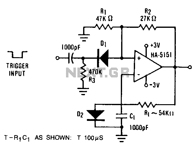
The circuit demonstrates the functionality of the HA-5151 as a battery-powered monostable multivibrator. In this configuration, the time constant is set to 0.632, simplifying the time constant equation to T = R1 * C1. Diode D2 is employed to...
The circuit illustrated in Figure (A) consists of resistors R1 and R2 with values ranging from 15 to 18 kΩ, and capacitors C1 and C2 with capacitance values between 0.01 µF and 10 µF. Figure (B) depicts the oscillation...
The MC74HC04 IC is a low cost CMOS Hex Inverter. I used this type mainly because, it is what I have, although you can use LS type but, with a little modification or exemptions. More: For 'HC' type: Always...
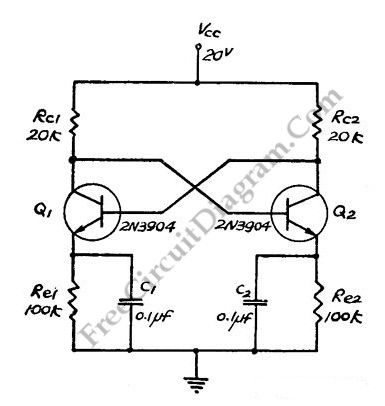
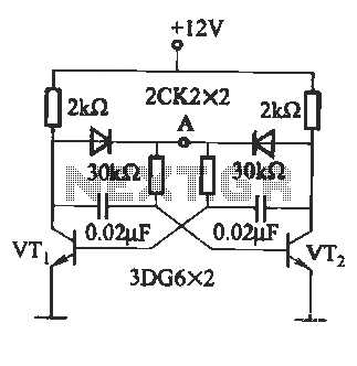
This flip-flop circuit functions as a free-running astable multivibrator, where the bases and collectors of both emitter-biased transistors are directly coupled. The switching action is facilitated by a capacitor in each emitter circuit, resulting in the generation of triangle...
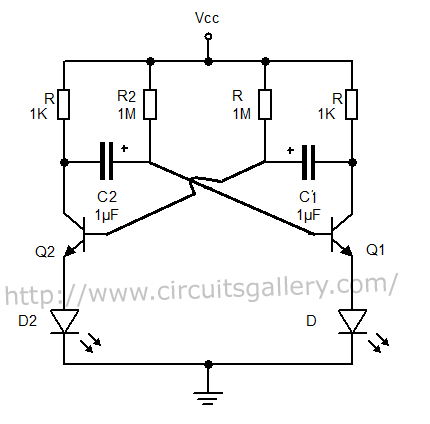
The output can also be taken from the collector terminals of the transistors, as illustrated in the circuit below. To understand the operation of the circuit, it is recommended to read about how a transistor functions as a switch. In...