
Basic UPS Power Supply
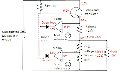
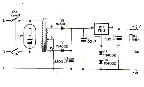
The described circuit functions as a basic Uninterruptible Power Supply (UPS), designed to provide a stable output for sensitive electronic devices. It features two output voltages: a regulated 5 Volt output suitable for powering microcontrollers, sensors, or other low-voltage devices, and an unregulated 12 Volt supply that can be utilized for higher power applications, such as motors or lighting.
The operation of the UPS circuit hinges on the seamless transition from the main power supply to the backup battery. Under normal conditions, the circuit draws power from the AC mains, converting it to the necessary DC voltages using a transformer and rectifier arrangement. The regulated 5 Volt output is typically achieved through a linear voltage regulator or a switching regulator, which ensures that fluctuations in the input voltage do not affect the output voltage, thus providing a stable power source.
In the event of a power outage, the circuit is designed to automatically switch to the backup battery. This is accomplished using a relay or a similar switching mechanism that detects the loss of mains power. The battery is kept charged during normal operation, ensuring it is ready to supply power when needed. The design includes protection features to prevent voltage spikes from reaching the regulated output, which could potentially damage connected devices.
In summary, this UPS circuit is an effective solution for providing reliable power to electronic devices. It combines both regulated and unregulated outputs, ensuring versatility in application, while also incorporating features that protect against power interruptions and voltage spikes.This circuit is a simple form of the commercial UPS, the circuit provides a constant regulated 5 Volt output and an unregulated 12 Volt supply. In the event of electrical supply line failure the battery takes over, with no spikes on the regulated supply.
🔗 External reference
Related Circuits
The circuit for the power amplifier has a power output of up to 1500W RMS and is commonly utilized in outdoor sound systems. The final image displays a series of power amplifiers that utilize 10 sets of power transistors....
This chapter presents a variety of circuits for basic power supplies, including both line-powered and inverter types, some of which feature regulators, modulation inputs, and additional functionalities. Several circuits have been reverse-engineered from actual commercial products, and others, designed...
Most power supplies regulate either their output voltage or current at a constant level, depending on the load resistance relative to the power supply's output voltage and current settings. This can be summarized as follows: To accomplish this, most...
Both circuits can synchronize trapezoidal wave voltage, which is converted into intermittent small rectangular pulses. Its working principle involves periodic operation in synchronization with the grid frequency of the zero-volt switching voltage of the DC chopper. Due to the...
A 12V portable and mobile power supply circuit design that can be constructed at a low cost and requires minimal circuitry. This circuit provides an output current of 1 amp, which is well stabilized and smoothed. The 12V portable power...
The ratio R1/R2 determines the amplitude of the triangle wave in relation to the square-wave output. The frequency of oscillation for both waveforms can be calculated using the equation: fo = 1/(4R3C1) * (R2/R1). In this circuit, R1 and R2...
Warning: include(partials/cookie-banner.php): Failed to open stream: Permission denied in /var/www/html/nextgr/view-circuit.php on line 713
Warning: include(): Failed opening 'partials/cookie-banner.php' for inclusion (include_path='.:/usr/share/php') in /var/www/html/nextgr/view-circuit.php on line 713