
From power fluctuations of one single-junction transistor trigger circuit
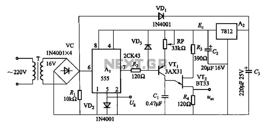
The described circuit operates by converting trapezoidal wave voltage into a series of small rectangular pulses that can be synchronized with an external power grid. The synchronization is achieved through a DC chopper, which operates at zero-voltage switching, reducing switching losses and improving efficiency. The 555 timer IC is configured in a comparator mode, which ensures that the output pulses maintain a consistent width despite fluctuations in input voltage.
The use of a low threshold voltage comparator minimizes the influence of voltage variations, allowing the circuit to maintain stable operation even under changing conditions. This design feature not only enhances the reliability of the circuit but also broadens the operational range of phase shifts, which is critical in applications where precise timing is essential.
The circuit's power supply stability is ensured by the 7812 voltage regulator, which outputs a fixed 12V, providing a reliable voltage source for the 555 timer and other components. The inclusion of an adjustment potentiometer (RP) enables fine-tuning of the output pulse width, allowing for precise control over the phase shift angle. This adaptability is particularly beneficial in applications requiring synchronization with varying grid frequencies.
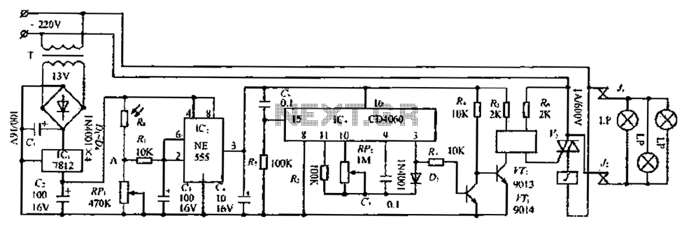
Overall, the circuit design effectively addresses the challenges associated with voltage fluctuations and phase shift management, making it suitable for various electronic applications where synchronization with grid power is crucial. Both circuits can trapezoidal wave voltage synchronous Here is converted into intermittent small rectangular pulse. Its working principle is to make periodic operating in synch ronization with the grid frequency of the zero volt switching voltage of the DC chopper. As a result of the low threshold voltage than the comparator, the impact of voltage fluctuations intermittent sync pulse width is minimal. Therefore, it makes the phase shift angle powered affect network voltage fluctuations greatly reduced, but also expanded phase shift range.
Circuit shown in Figure 16-10. It uses 555 IC Ai limit for single inverter voltage comparator; using 7812 three terminal integrated voltage regulator A2 fixed to provide a stable power supply. Adjustment potentiometer RP, can change the output pulse to e phase shift angle.
Related Circuits
This is a simple game circuit designed for multiplayer enjoyment. The objective is to score one hundred points within a limited timeframe. To restart the game, the S1 button switch must be pressed. It is important to ensure that...
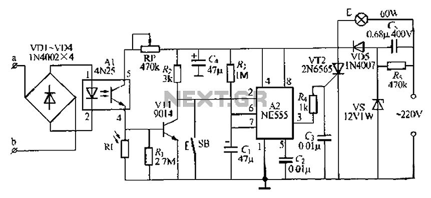
The lamp base circuit integrates an NE555 timer and optocouplers to automatically activate the light when a phone call is received at night. The lamp will self-extinguish after a delay. Additionally, a switch allows manual control of the lamp....
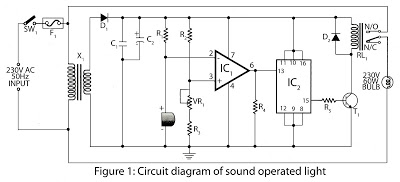
This is a hobby circuit designed for electronics enthusiasts that can turn on and off devices such as lights, fans, and radios in response to the sound of a clap. The sound is detected by a small microphone, which...
There have been several requests for a quiz circuit, leading to the development of a design featuring four inputs that can be easily modified. This circuit employs four integrated circuits (ICs) and includes four input circuits with independent outputs,...
The circuit presented is designed to prevent burning one's tongue by monitoring the temperature of coffee. It consists of a voltage regulator, a temperature-to-voltage converter, a comparator, and two LEDs. In general, the circuit operates as follows: if the...
The circuit consists of three parts: a light control section, a time control section, and a power supply section. The light control section utilizes a photoresistor (Rg) and a variable resistor (RP) to detect light levels. During the day,...