
Bass And Treble Controller Circuit Based On The Classic Baxandall Tone Control Circuitry
The Bass and Treble Controller Circuit is designed to adjust the low and high-frequency response of audio signals, allowing for enhanced sound quality and tailored audio experiences. The circuit typically employs operational amplifiers (op-amps) configured in a feedback arrangement to achieve the desired tone control characteristics.
The classic Baxandall configuration utilizes two primary stages: one for bass control and another for treble control, each incorporating variable resistors (potentiometers) to adjust the gain of the respective frequency bands. The circuit generally includes capacitors to filter specific frequency ranges, ensuring that the adjustments made do not adversely affect the overall audio signal integrity.
In a typical implementation, the bass control section may consist of a low-pass filter, which allows frequencies below a certain threshold to pass while attenuating higher frequencies. Conversely, the treble control section functions as a high-pass filter, allowing frequencies above a designated point to be amplified while reducing lower frequencies.
The output of the circuit is designed to be connected to a power amplifier or directly to a speaker system, enabling users to modify their audio output dynamically. The use of high-quality components, such as low-tolerance resistors and capacitors, is recommended to maintain fidelity and minimize noise in the audio signal.
This circuit is particularly valuable in audio applications where user preference for low and high frequencies can significantly impact the listening experience, making it a staple in both consumer electronics and professional audio equipment.The following circuit shows about Bass And Treble Controller Circuit. This circuit built based on the classic Baxandall tone control circuitry .. 🔗 External reference
Related Circuits
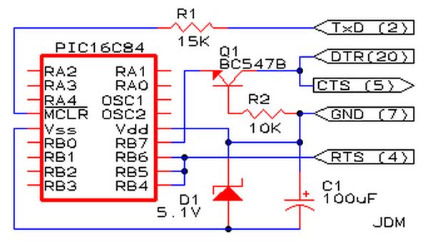
Affordable PIC Programmer. This programmer is compatible solely with the PIC16F84 microcontroller. It is reliable, as it rarely encounters errors, and functions well with nearly all computer systems, in contrast to some alternatives. The PIC programmer designed for the PIC16F84...
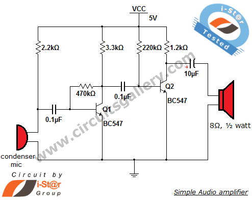
This circuit diagram is a simple and effective design for amplifying weak signals from a capacitive condenser microphone. It is suitable for sound sensing applications and various automatic robotic sensors. While a more complex audio amplifier circuit using the...
This file is copyrighted. The individual who uploaded this work and first used it in licensing holds the rights. The provided information indicates that the file is protected by copyright, with the rights belonging to the individual who initially uploaded...
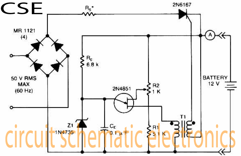
The accumulator charger circuit must provide a voltage that matches the specifications of the batteries being charged. For a 12-volt accumulator, the output voltage should not exceed 12 volts, nor should it fall significantly below this threshold. Failure to...
In many countries, it is now mandatory or at least recommended to have a rear fog light on a trailer, with the additional requirement that when the trailer is attached to the vehicle, the rear fog light of the...
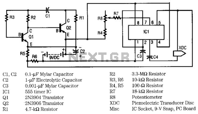
This circuit utilizes two transistors and one integrated circuit (555 timer IC) to generate a pulsating ultrasonic frequency. Transistors Q1 and Q2 are configured in a direct-coupled oscillator arrangement. The frequency of the oscillator is determined by capacitor C1....