
Ultrasonic Pest Repeller Circuit

The circuit design incorporates a direct-coupled oscillator formed by the complementary transistors Q1 (NPN) and Q2 (PNP). This configuration allows for efficient oscillation, with the frequency being primarily determined by the capacitor C1, which sets the timing characteristics of the oscillator. The emitter of Q2 serves as the output point for this oscillation, providing a signal that is subsequently routed to pin 7 of the 555 timer IC (IC1).
The 555 timer is configured in a stable multivibrator mode, where its operation is influenced by capacitor C3. This capacitor plays a crucial role in determining the frequency of the output signal at pin 3 of the IC. The output signal at pin 3 is modulated by the audio frequency produced by the oscillator, resulting in a composite ultrasonic waveform.
Capacitor C3 ensures that the generated frequency remains in the ultrasonic range, effectively beyond the limits of human hearing. The final output, which combines the modulated ultrasonic frequency, is accessed at pin 3 of the 555 timer. This signal is then coupled to a piezoelectric transducer via capacitor C4, which converts the electrical signal into ultrasonic sound waves.
In summary, this circuit effectively combines the properties of transistors and a 555 timer to create an ultrasonic generator, with careful selection of capacitors to define the operational frequencies, ensuring the output is suitable for applications requiring ultrasonic sound generation. This circuit uses two transistors and one IC (555 timer IC) to produce a pulsating ultrasonic frequency. Transistors Ql and Q2 are connected in a direct-coupled oscillator. The frequency of that oscillator is set by capacitor CI. The oscillator output is taken from the emitter of Q2 to pin 7 of IC1. Transistor Ql is an npn transistor, and Q2 is a pnp transistor. The signal of pin 7 on IC1 causes the output signal appearing on pin 3 to be modulated or varied by the audio frequency developed by Ql and Q2.
The IC itself is connected as a stable multivibrator with a frequency that is determined by C3. Capacitor C3 sets the basic frequency to be well above the human hearing range (ultrasonic). The combined modulated ultrasonic frequency appears on pin 3 of IC1, where it is coupled by capacitor C4 to the piezoelectric transducer.
Related Circuits
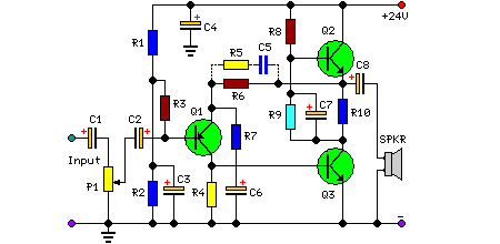
This solid-state push-pull single-ended Class A circuit is designed to deliver sound quality comparable to valve amplifiers, providing an output power of 6.9W measured across an 8 Ohm loudspeaker cabinet load. It features reduced total harmonic distortion (THD), increased...
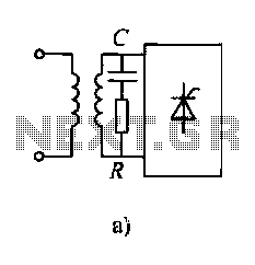
Diodes and thyristors have limited tolerance to over-current and over-voltage conditions. Short-term exposure to excessive voltage or current can damage these components and prevent them from achieving their full potential. The parameters of these devices should be determined based...

This unique logic-power-converter design allows for a switchable output of 3.6 V or 5 V at 200 mA using four AA cells. The supply features a MOSFET switch that can connect to a lithium backup battery, providing a 3.4...
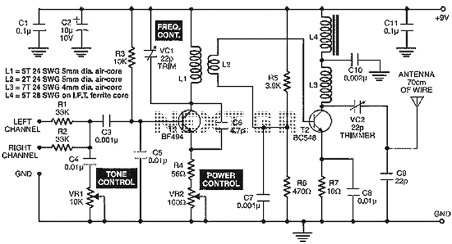
This house FM transmitter for your stereo or any other amplifier provides a strong signal strength up to a distance of 500 meters with a power output of about. This FM transmitter is designed to enhance audio transmission capabilities for...
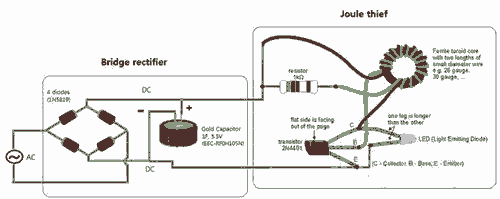
Breathe down and come out on the bright flashlight. In order to promote the voltage, pieces of a highly skilled Joule thief circuit have been used. The Joule thief circuit is a minimalist, low-power boost converter designed to extract energy...
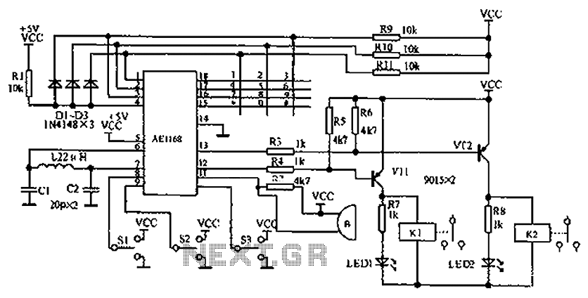
The circuit diagram represents an enhanced lock system, the AE1169, which is an upgrade of the AE1168 model. When the lock button is pressed, the AE1168 utilizes a keyboard scanning method to identify the corresponding button. Based on the...