
Fog Lamp Switch Circuit
This circuit design effectively addresses the need for compliance with regulations regarding trailer fog lights while ensuring functionality and safety. The use of a relay allows for the automatic disconnection of the vehicle's rear fog light when a trailer is connected, preventing confusion and enhancing visibility for other drivers. The inclusion of a reed contact as a sensing element provides a reliable means of detecting the presence of the trailer. The specifications for the coil L1 are critical; it must be optimized to ensure that the relay is activated promptly without unnecessary power draw or overheating.
In practical implementation, the circuit should be housed in a durable enclosure to protect against environmental factors such as moisture and vibration, which are common in automotive applications. Proper insulation and strain relief should be considered for all connections to maintain circuit integrity over time. Additionally, the selection of high-quality components, such as the relay and reed switch, will contribute to the longevity and reliability of the system. Testing under various conditions, including different trailer loads and environmental scenarios, is essential to validate the design before deployment. This ensures that the system operates as intended, providing safety and compliance with applicable regulations.In most countries it is now mandatory or at least recommended to have a rear fog light on a trailer with the additional requirement that, when the trailer is coupled to the car, the rear fog light of the towing car has to be off. The circuit shown here is eminently suitable for this application. The circuit is placed near the rear fog light of the car. The 12-V connection to the lamp has to be interrupted and is instead connected to relay contacts 30 and 87A (K1, K3). When the rear fog light is turned on it will continue to operate normally. If a trailer with fog light is now connected to the trailer connector (7- or 13-way, K2), a current will flow through L1.
L1 is a coil with about 8 turns, wound around reed contact S1. S1 will close because of the current through L1, which in turn energizes relay Re1 and the rear fog light of the car is switched off. The fog light of the trailer is on, obviously. The size of L1 depends on reed contact S1. The fog lamp is 21 W, so at 12 V there is a current of 1. 75 A. L1 is sized for a current between 1. 0 and 1. 5 A, so that it is certain that the contact closes. The wire size has to be about 0. 8 mm. The relay Re1 is an automotive relay that is capable of switching the lamp current. The voltage drop across L1 is negligible. 🔗 External reference
Related Circuits
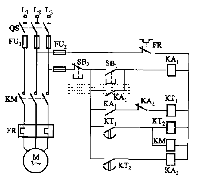
The circuit illustrated in Figure 3-76 employs two time relays, KTi and KTz, to manage the operation and downtime of a motor. The circuit utilizes two time relays to provide precise control over the motor's operational cycles. Relay KTi is...
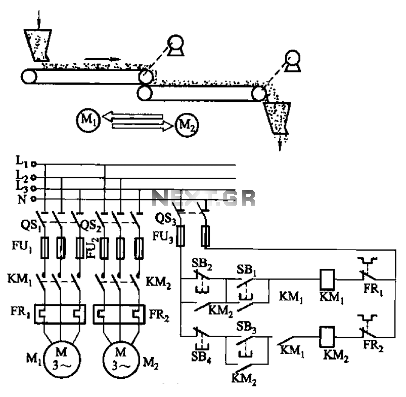
The circuit depicted in Figure 3-86 utilizes a line utilization time relay to control two motors, starting one before the other after an initial stall. The time relay KTi can be adjusted to modify the starting interval of the...
A modulated current is supplied by the integrated rotational speed sensor KMI 15/x. This current signal needs to be converted into a ground-referenced voltage signal. The KMI 15/x sensor operates by generating a modulated current proportional to the rotational speed of...
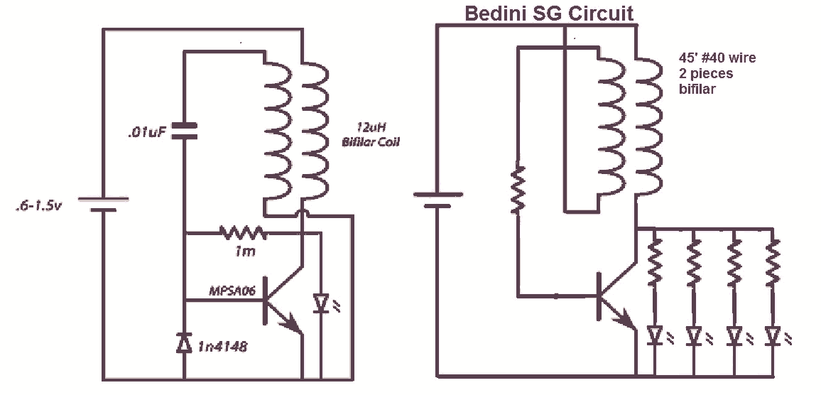
It would be beneficial to obtain schematics of the Joule Thief and Bedini oscillator circuit connections. This is an area that has not been previously explored. The schematic on the left was sourced from the Energetic Forum, while the...
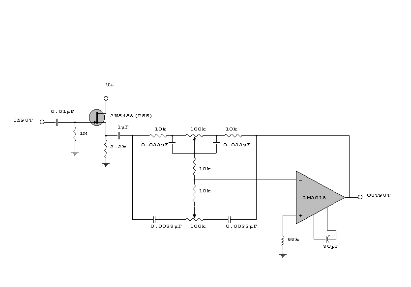
This circuit is a simple series tone control circuit. It utilizes the surgical amplifier LM301A. The JFET 2N3684 provides high input impedance and low noise for the unbuffered operational amplifier, which operates in an equalizer (EQ) configuration. Further details...
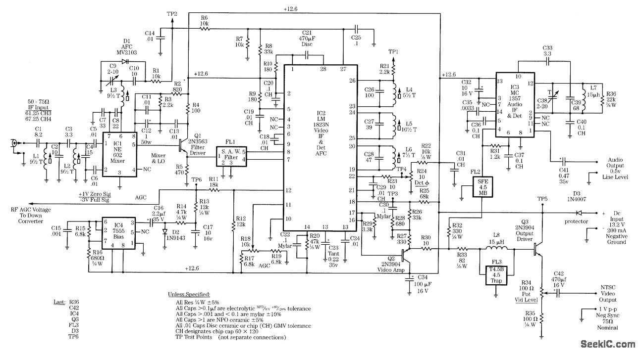
Radio-frequency schematics (also see NE602 datasheet and application note). This page contains electronic circuits related to RF receivers. This index features a broad collection of RF receiver circuits. Radio-frequency (RF) schematics are essential for designing and implementing circuits that operate...
Warning: include(partials/cookie-banner.php): Failed to open stream: Permission denied in /var/www/html/nextgr/view-circuit.php on line 713
Warning: include(): Failed opening 'partials/cookie-banner.php' for inclusion (include_path='.:/usr/share/php') in /var/www/html/nextgr/view-circuit.php on line 713