
bass glow
The circuit utilizes an inverter designed to convert a low DC voltage from a battery into a higher AC voltage suitable for driving an electroluminescent (EL) sheet. The inverter circuit typically comprises key components such as a transformer, transistors or MOSFETs for switching, and capacitors for filtering. The design may include a feedback mechanism to stabilize the output voltage, ensuring consistent brightness of the EL sheet.
However, the noted higher-than-expected battery consumption suggests inefficiencies in the circuit. This could be due to factors such as inadequate component ratings, suboptimal switching frequencies, or insufficient power management techniques. It is advisable to analyze the circuit layout for potential improvements, such as optimizing the transformer turns ratio or selecting low-loss components.
The provided video serves as a visual reference for the inverter's operation, showcasing the EL sheet's illumination. Users interested in further enhancing the circuit's performance may consider integrating a more efficient power supply or exploring alternative inverter designs that reduce energy consumption while maintaining output quality.Since I used a ready-made inverter circuit to drive the EL sheet, this diagram is incomplete and also I`d say the battery consumption is much higher than it should be. As seen in the comments, an AVI video file is available without sound (as I used my webcam to record it).
If you are interested, you can download it from the address below. 🔗 External reference
Related Circuits
All errors in circuit diagrams, documents, and layout have been corrected. The circuit shown is functional and operational. It is important to note that Q2 is sensitive and can be easily damaged by incorrect connections, shorts, over-voltage, or excessive...

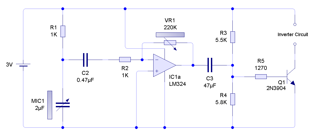
The circuit operates by processing an input signal through IC1-1 and a fourth-order low-pass filter, which provides a slope of 24 dB/octave with a cutoff frequency (fc) of 70 Hz and an amplification of 8.2 dB. The output from...
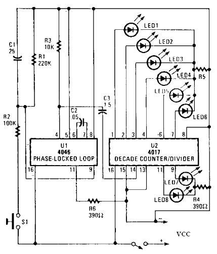
An electronic circuit for a roulette wheel can be constructed using a 4046 Phase-Locked Loop (PLL) that includes a Voltage Controlled Oscillator (VCO), two phase comparators, a source follower, and a Zener diode to generate a low-frequency pulsed output...
The advantages of a guitar amplifier include its straightforward circuitry, even with relatively high power outputs, and a built-in degree of loudspeaker protection provided by capacitor C8, which prevents voltage supply from reaching the loudspeakers in the event of...
Upgrading to a 3-prong AC cord is a common modification, as is the replacement of filter capacitors. Switching coupling capacitors to brands like Orange Drops or other boutique options is also popular, often enhancing the appeal in online auctions....
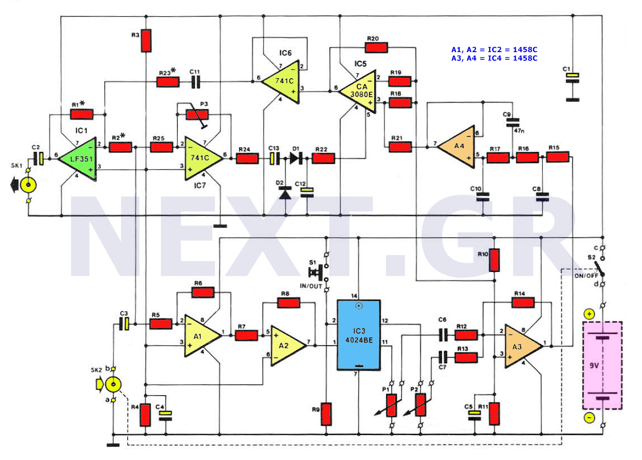
The sub-harmonic bass generator is a sound-producing unit designed for guitars, capable of generating sounds similar to those of a bass guitar. This device employs an octave generator that operates differently from traditional sound coloring methods such as filtering...